eFlow102NV Series Power Supply/Chargers Models Include: eFlow102NV/ eFlow102NXV - 10A @ 12VDC eFlow102N8V/ eFlow102NX8V eFlow102N8DV/ eFlow102NX8DV eFlow102N16V/ eFlow102NX16V eFlow102N16DV/ eFlow102NX16DV - 10A @ 12VDC - Eight (8) Fused Outputs - 10A @ 12VDC - Sixteen (16) Fused Outputs - 10A @ 12VDC - Eight (8) PTC Protected Outputs - 10A @ 12VDC - Sixteen (16) PTC Protected Outputs Installation Guide Rev. 102NVRP052213 More than just power.TM Installing Company: ________________ Service Rep.
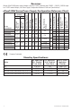
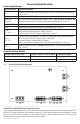
Overview: Altronix eFlow102NV power supply/chargers convert a 220VAC (working range 198VAC - 256VAC), 50/60Hz input to a 12VDC nominal output (see Power Supply Configuration Reference Chart and Specifications). PD8 10.035A/ 15A/ 10A 2.1A 760 13.2 250V 32V 10.03- 10.035A/ 15A/ 10A 2.1A 760 13.2 13.2 250V 32V 9.7813.2 10.035A/ 15A/ 10A 2.1A 760 13.2 250V 32V PD8CB PD16W 2 - PD8 PD16WCB 2 - PD8CB Fused Outputs Ratings Accommodates up to 12AH Batteries 10.03- 10.035A/ 15A/ 10A 2.1A 760 13.2 13.
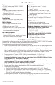
Specifications: Input: • 220VAC (working range 198VAC - 256VAC), 50/60Hz. Output: • For output voltage and supply current refer to eFlow102NV series Power Supply Configuration Reference Chart, pg. 2. • Auxiliary output rated @ 1A (unswitched). • Overvoltage protection. Fuse Ratings: • Refer to eFlow102NV Series Power Supply Configuration Reference Chart, pg. 2. Battery Backup: • Built-in charger for sealed lead acid or gel type batteries. • Maximum charge current 1.54A.
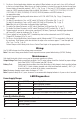
5. For Access Control applications batteries are optional. When batteries are not used, a loss of AC will result in the loss of output voltage. When the use of stand-by batteries is desired, they must be lead acid or gel type. Connect battery to terminals marked [– BAT + ] (Fig. 1g, pg. 5). Use two (2) 12VDC batteries connected in series for 24VDC operation (battery leads included).
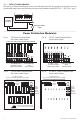
Terminal Identification: Power Supply/Charger Terminal Legend Function/Description L, N Connect 220VAC 50/60Hz to these terminals: L to hot, N to neutral (non power-limited) (Fig. 1a, pg. 5). – DC + 12VDC nominal @ 10A continuous output (power-limited output) (Fig. 1h, pg. 5). Trigger EOL Supervised Fire Alarm Interface trigger input from a short or FACP. Trigger inputs can be normally open, normally closed from an FACP output circuit (power-limited input) (Fig. 1d, pg. 5).
Fig. 2 - Battery Trouble Indication Wire one leg of a power-limited power source to the indicating lamp. Wire the second leg of the power source to the indicating lamp in series with the battery fail relay contact terminals marked [BAT FAIL - C, NO] (Fig. 2, pg. 6). AC FAIL POWER SOURCE BAT FAIL NC C NO NC C NO RED INDICATING LAMP –––––––––––––––––––––––––––––––––––––––––––––––––––––––––––––––––––––––––––––––––––––––––– Power Distribution Module(s): Fig. 3a - PD8 Power Distribution Board Fig.
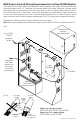
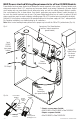
Fig. 5 - eFlow102NV Configuration Enclosure Edge of Enclosure Tamper Switch (included) To Access Control Panel or UL Listed Reporting Device Ground Lug L PD8/PD8CB G N 220VAC power mains PD16W/ PD16WCB AC1 AC FAIL NC C NO NC C NO BAT FAIL Battery & AC Supervision Circuit DC Output to Devices* (refer to Fig. 3a, 3b, 4a, 4b for board configuration, pg.
NEC Power-Limited Wiring Requirements for eFlow102NV Models: Power-limited and non power-limited circuit wiring must remain separated in the cabinet. All power-limited circuit wiring must remain at least 0.25” away from any non power-limited circuit wiring. Furthermore, all power-limited circuit wiring and non power-limited circuit wiring must enter and exit the cabinet through different conduits. One such example of this is shown below.
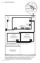
Fig. 7 - eFlow102NXV Configuration Enclosure Edge of Enclosure Tamper Switch (included) To Access Control Panel or UL Listed Reporting Device - DC + Ground Lug Battery & AC Supervision Circuit L G AC1 N NC C NO NC C NO AC FAIL BAT FAIL AC DC TRIGGER EOL SUPERVISED NO GND RESET - BAT + Battery Connection +AUX- power-limited 220VAC power mains PD8/PD8CB PD8/PD8CB DC Output to Devices* (refer to Fig. 3a, 3b, 4a, 4b for board configuration, pg. 6) DC Output to Devices* (refer to Fig.
NEC Power-Limited Wiring Requirements for eFlow102NX Models: Power-limited and non power-limited circuit wiring must remain separated in the cabinet. All power-limited circuit wiring must remain at least 0.25” away from any non power-limited circuit wiring. Furthermore, all power-limited circuit wiring and non power-limited circuit wiring must enter and exit the cabinet through different conduits. One such example of this is shown below.
Enclosure Dimensions (BC300): eFlow102NV, eFlow102N8V, eFlow102N8DV, eFlow102N16V, eFlow102N16DV 13.5” x 13” x 3.25” (342.9mm x 330.2mm x 82.6mm) 1.40” (35.6mm) 4.85” (123.2mm) 4.85” (123.2mm) 1.40” (35.6mm) 1.20” (30.5mm) 0.75” (19.1mm) 3.25” (82.6mm) 1.20” (30.5mm) 0.75” (19.1mm) 12.5” (317.5mm) 11.0” (279.4mm) 1.20” (30.5mm) 0.9375” (23.8mm) 1.40” (35.6mm) 1.40” (35.6mm) 5.10” (129.5mm) 5.10” (129.5mm) 13.0” (330.2mm) 6.5625” (166.7mm) 5.10” (129.5mm) 0.9375” (23.8mm) 3.25” (82.6mm) 3.
Enclosure Dimensions (BC400): eFlow102NXV, eFlow102NX8V, eFlow102NX8DV, eFlow102NX16V, eFlow102NX16DV 15.5” x 12” x 4.5” (393.7mm x 304.8mm x 114.3mm) 1.5” (38.1mm) 4.615” (117.2mm) 4.615” (117.2mm) 1.5” (38.1mm) 1.75” (44.5mm) 1.25” (31.8mm) 4.5” (114.3mm) 1.1” (27.9mm) 12.23” (310.6mm) 4.5” (114.3mm) 1.1” (27.9mm) 1.375” (34.9mm) 1.5” (38.1mm) 1.25” (31.8mm) 1.5” (38.1mm) 0.91” (23.1mm) 0.91” (23.1mm) 1.125” (28.6mm) 15.5” (393.7mm) 2.0” (50.8mm) 2.0” (50.8mm) 5.0” (127.0mm) 0.79” (20.
Appendix A - UL Listed Compatible Devices –––––––––––––––––––––––––––––––––––––––––––––––––––––––––––––––––––––––––––––––––––––––––– A.1 Four (4) Wire Smoke Detectors Table A-1 below lists four (4) wire smoke detectors compatible with eFlow102NV output.
eFlow Power Supply/Chargers can be Controlled and Monitored while Reporting Power/Diagnostics from Anywhere over the Network... LINQ2 - Network Communication Module LINQ2 provides remote IP access to real-time data from eFlow power supply/chargers to help keep systems up and running at optimal levels.
Notes: Altronix is not responsible for any typographical errors. –––––––––––––––––––––––––––––––––––––––––––––––––––––––––––––––––––––––––––––––––––––––––––––––––––––––––––––––– 140 58th Street, Brooklyn, New York 11220 USA | phone: 718-567-8181 | fax: 718-567-9056 website: www.altronix.com | e-mail: info@altronix.
Power Supply/Chargers Operating Guide Models Include: Model eFlow102NV, eFlow102NV8, eFlow102N8DV, eFlow102N16V, eFlow102N16DV eFlow102NXV, eFlow102NX8V, Flow102NX8DV, eFlow102NX16V, eFlow102NX16DV Output Input 220VAC, 50/60Hz 12VDC 24VDC 2.1A 10A – Auxiliary Power-Limited Ripple Output (unswitched) Voltage 1A 760mV Overview: The eFlow102NV series power supply/chargers convert a 220VAC, 50/60Hz input to a 12VDC output.