IP over Coax Receiver Installation Guide Models Include: eBridge16CR - Sixteen (16) Channel Receiver Z1409 I.T.E. 43KC Rev. 072412 More than just power.
Overview: The eBridge16CR is a CAT5 to Coax cable Ethernet receiver. The receiver enables fast 10/100Base-T Ethernet digital communication to be received over Coax cable. This plug and play unit facilitates system upgrades from analog to IP cameras/devices utilizing existing legacy Coax and eliminating the costs and labor associated with installing new network cabling.
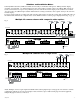
2. Unit should be located in proximity to ethernet switch/network, NVR or video server. 3. Connect UL Listed 24VAC Class 2 plug-in transformer or 24VDC/56VDC (polarity not observed) UL Listed Class 2 power supply to jack marked [Power Input] using two pin plug in connector (supplied) (Fig. 1, pg. 2). Use 22AWG-16AWG wire for this connection. 4. Connect structured cable from ethernet switch/NVR (network video server) to RJ45 jack marked [10/100BaseT] (Fig. 1, pg. 2). 5.
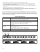
Single IP camera shown with composite video option: Fig. 2 eBridge1CT eBridge1CT eBridge1CT Input: 12VDC/275mA, 24VDC/110mA, 16VAC/375mA, 24VAC/200mA. Blue LED Coax link status. RJ45 LEDs Yellow - Speed Green - Activity Green LED Power Composite Video Cable To Monitor eBridge1CT Composite Video Cable To Monitor Input: 12VDC/275mA, 24VDC/110mA, 16VAC/375mA, 24VAC/200mA. Blue LED Coax link status.
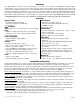
Solutions and Installation Notes: Currently Matrix Switchers, DVRs and NVRs do not readily accommodate multi-picture (Matrix) monitor display capability (typically 4X4 – 16 channel display) for some of the higher resolution cameras. In addition HD cameras use a wide screen format (16:9 aspect ratio). This may not fit as well into the matrix display as the standard screen format (4:3 aspect ratio).
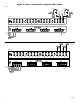
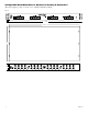
eBridge16CR Rack Mount Chassis Mechanical Drawing & Dimensions: (H x W x D approx.) 1.625” x 19.125” x 8.5” (42mm x 486mm x 216mm) Fig. 6 19.125" .75" 17.625" 8.5" 1.
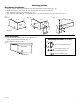
Mounting Options: Rack Mount Installation 1- Remove and discard factory installed screws from both sides of rack chassis (Fig. 7a). 2- Install mounting brackets (A) on the left and right side of rack chassis using the four (4) flat head screws (B) (included) (Fig. 7b). 3- Place unit into desired EIA 19” rack position and secure with mounting screws (not included) (Fig. 7c). Fig. 7 Fig. 7a Fig. 7b Fig.
Notes: Altronix is not responsible for any typographical errors. 140 58th Street, Brooklyn, New York 11220 USA, 718-567-8181, fax: 718-567-9056 website: www.altronix.com, e-mail: info@altronix.com, Lifetime Warranty, Made in U.S.A.