
Installation Instructions Manual
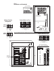

Transformer
underneath
power supply
board
Power
Switch
White Lead
Black Lead
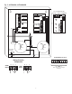
Used on PTC Models
(example: ALTV248300CBM)
N
COMMON POWER OUTPUTS
P
FUSED POWER OUTPUTS
D1
INPUT
N P S
R1
LED
MAIN
FUSE
MAIN
FUSE
F1 F2 F3 F4 F5 F6 F7 F8
Used on PTC Models
(example: ALTV248300CB)
N
COM
MON POWER OUTPUTS
P
FUSED POWER OUTPUTS
D1
INPUT
NPS
R1
LED
MAIN
FUSE
MAIN
FUSE
F1 F2 F3 F4 F5 F6 F7 F8
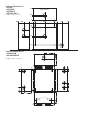
24VAC or 28VAC circuit
breakered output 1
(Follow same procedure using
terminals 2P & N thru 8P & N
cir
cuit breakered outputs 2 thru 8)
- 5 -
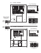
Fig. 3
ALTV248300 • ALTV248300CB
Fig. 4 - ALTV248300M • ALTV248300CBM
24VAC or 28VAC
fused or PTC protected outputs
1 through 8.
Terminal Blocks for Fig. 3
Terminal Blocks for Fig. 4
24VAC or 28VAC
fused or PTC protected outputs
1 through 8.
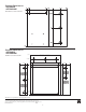
NP S
NP S
24VAC
Output
(Yellow) (Black)
(Black) (Yellow)
28VAC
Output
Voltage Selection
Configuration