
Installation Instructions Manual

- 4 -
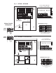
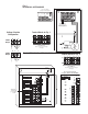
Fig. 1 - ALTV248 • ALTV248CB
XFMR
11
5VAC input
50/60 Hz,
White Lead
Black
Lead
MAIN FUSE
ON OFF
N
COMMON POWER OUTPUTS
P
FUSED POWER
OUTPUTS
1 2
3 4 5 6 7 8
D1
INPUT
R1
LED
Used on PTC Models
(example: ALTV248CB)
NPS
NPS
24VAC or 28VAC circuit
breakered output 1
(Follow same procedure using
terminals 2P & N thru 8P & N
circuit breakered outputs 2 thru 8)
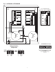
Fig. 2 - ALTV248175 • ALTV248175CB
XFMR
White Lead
Power
Switch
Black
Lead
115VAC input
50/60 Hz,
1.5 amps
24 VAC or 28VAC fused output 1
(Follow same procedure
using terminals 2P & N
thru 8P & N fused
outputs 2 thru 8)
Used on PTC Models
(example: ALTV248175CB)
N
COMMON POWER OUTPUTS
P
FUSED POWER OUTPUTS
D1
INPUT
NPS
R1
LED
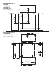
MAIN
FUSE
MAIN
FUSE
F1 F2 F3 F4 F5 F6 F7 F8
Back Panel of Enclosure
24VAC or 28VAC fused or PTC
protected outputs 1 through 8.
Terminal Blocks for Fig. 1
24VAC or 28VAC
fused or PTC protected outputs
1 through 8.
Terminal Blocks for Fig. 2
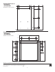
NP S
NP S
24VAC
Output
(Yellow) (Black)
(Black) (Yellow)
28VAC
Output
Voltage Selection
Configuration