
Installation Instructions User Manual

ALTV244series - 3 -
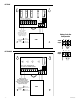
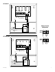
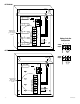
4. Connect AC power to the black and white flying lead of the transformer (Fig. 1, pg. 4).
Units with line cord installed skip Instruction #4.
Use 18 AWG or larger for all power connections (Battery, AC output).
5. Measure output voltage before connecting devices. This helps avoiding potential damage.
CAUTION: Determine the maximum operating voltage of the equipment being powered before adjusting the
output voltage.
6. Connect devices to the terminals marked [1P - 1N through 4P - 4N] on PD4/PD4CB board, carefully observing
correct polarity (Fig. 1, pg. 4).
7. Slide switch SW1 to ON position (Models ALTV244 and ALTV244CB), (Fig. 1, pg. 4).
Turnmainswitchonallothermodelstothe“RESET”(ON)position.
8. GreenLEDwillilluminatewhenunitispowered.
9. Upon completion of the wiring, secure enclosure door with screws (supplied).
Caution:Equipmenttobeinstalled/servicedbyauthorized/trainedpersonnelonly.
Shutbranchcircuitpowerbeforeinstalling/servicingequipment.
WARNING: To reduce the risk of fire or electric shock, do not expose the unit to rain or moisture.
This installation should be made by qualified service personnel and should conform to the National
Electrical Code and all local codes.
Terminal Identification:
PD4/PD4CB - Distribution Module
1P - 4P Positive AC output.
1N - 4N Negative AC output.
Thelightningflashwitharrowheadsymbolwithinanequilateraltriangleisintendedtoalerttheusertothe
presenceofaninsulatedDANGEROUSVOLTAGEwithintheproductsenclosurethatmaybeofsufficient
magnitude to constitute an electric shock.
Theexclamationpointwithinanequilateraltriangleisintendedtoalerttheusertothepresenceofimportant
operating and maintenance (servicing) instructions in the literature accompanying the appliance.
CAUTION: To reduce the risk of electric shock do not open enclosure. There are
nouserserviceablepartsinside.Referservicingtoqualifiedservicepersonnel.