
Installation Instructions Owner's manual


- 2 - UL Listed Isolated Series
Overview:
These Altronix Isolated CCTV Power Supplies provide 24VAC distributed via eight (8) or sixteen (16) fuse or
PTC protected isolated outputs for powering CCTV Cameras, heaters and other video accessories.
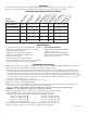
Isolated Power Supply Reference Chart:
ALTV248ULHi 24VAC 12.5 amp 8 - x 1.6 amp 3 amp
ALTV248ULCBHi 24VAC 12.5 amp 8 x - 1.6 amp 3 amp
ALTV248ULMi 24VAC 12.5 amp 8 - x 1.6 amp 3 amp
ALTV248ULCBMi 24VAC 12.5 amp 8 x - 1.6 amp 3 amp
ALTV2416ULi 24VAC 25 amp 16 - x 1.6 amp 6 amp
ALTV2416ULCBi 24VAC 25 amp 16 x - 1.6 amp 6 amp
Add suffix “3” for 3-wire line cord (e.g. ALTV248ULHi3).
Specifications:
Installation Instructions:
Wiring methods shall be in accordance with the National Electrical Code/NFPA 70/NFPA 72/ANSI, and with all local
codes and authorities having jurisdiction. Product is intended for indoor use only.
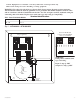
1. Mount the unit in desired location. Mark and predrill holes in the wall to line up with the top two keyholes in the
enclosure. Install two upper fasteners and screws in the wall with the screw heads protruding. Place the enclosure’s
upper keyholes over the two upper screws, level and secure. Mark the position of the lower two holes. Remove the
enclosure. Drill the lower holes and install the two fasteners. Place the enclosure’s upper keyholes over the two upper
screws. Install the two lower screws and make sure to tighten all screws (Enclosure Dimensions, pg. 6-7). Secure
enclosure to ear
th ground (Figs. 1-3, pgs. 3-5).
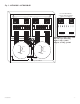
2. Set power switch to OFF position on all models (Figs. 1-3, pgs. 3-5).
3.
All units are factory set for 24VAC operation.
4. Secure green lead to earth ground. Connect AC power to the black and white flying leads of the transformer(s)
(Figs. 1-3, pgs. 3-5). Use 18 AWG or larger for all power connections.
Keep power-limited wiring (PTC protected outputs only) separate from non power limited wiring.
Minimum .25” spacing must be pr
ovided. Use separate knockouts
5. Measure output voltage before connecting devices. This helps av
oid potential damage.
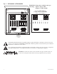
Terminals marked [1A - 8A] and [1B - 8B] are of the same polarity (phase).
6. Connect CCTV cameras to output terminals using the following procedure:
Camera 1 to output 1A & 1B. Camera 5 to output 5A & 5B.
Camera 2 to output 2A & 2B. Camera 6 to output 6A & 6B.
Camera 3 to output 3A & 3B. Camera 7 to output 7A & 7B.
Camera 4 to output 4A & 4B. Camera 8 to output 8A & 8B.
7. Set power switch on all models to the “RESET” (ON) position (Figs. 1-3, pgs. 3-5).
8. Upon completion of wiring, secure enclosure door with scre
ws (supplied).
Altronix
Model Number
Output Current
(max per output)
Total Output
Current
Output Voltage
115VAC
50/60Hz Input
Current
PTC Protected
Outputs (Class 2
Power Limited
for dry locations)
Fuse Protected
Outputs
Number of
Outputs
• UL Listed for Commercial CCTV Equipment (UL2044).
CUL Listed - CSA Standard C22.2 No.1-98, Audio,
Video and Similar Equipment.
• Individual electronically isolated outputs.
• Illuminated master Power ON/OFF switch
w/built in circuit breaker.
• Unit maintains camera synchronization.
• Ease of installation saves time & eliminates costly labor.
• Spare fuses included (on fuse protected models).
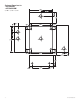
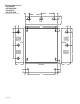
Enclosure Dimensions:
ALTV248ULMi, ALTV248ULCBMi:
8.5"H x 7.5"W x 3.5"D
ALTV248ULHi, ALTV248ULCBHi,
ALTV2416ULi and ALTV2416ULCBi:
13"H x 13.5"W x 3.25"D