
Installation Instructions Manual


ALTV1224DCseries - 3-
WARNING: To reduce the risk of fire or electric shock, do not expose the unit to rain or moisture.
This installation should be made by qualified service personnel and should conform to all local codes
and in accordance with the National Electrical Code.
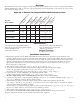
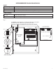
ALTV1224DC/CB Terminal Identification:
OLS127 - Power Supply
Terminal Legend Function/Description
L, G, N 115VAC 50/60 Hz connections
– DC +
12VDC or 24VDC @ 4 amp total continuous output.
– BAT + Stand-by battery connections. Maximum charge rate .5 amp.
PD8/PD8CB - Distribution Module
1P - 8P Positive DC power outputs.
1N - 8N Negative DC power outputs.
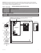
D
oor
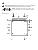
CAUTION: De-energize unit prior to servicing. For continued protection against
fire hazard replace fuse with the same type and rating 5A, 250V.
Do not expose unit to rain or moisture.
N
C O M M ON P OW E R O U TP U TS
P
F U S E D P OW E R O UT P UT S
1 2 3 4 5 6 7 8
D1
INPUT
R1
LED
S
witch Position:
2
4VDC = SW1 OPEN
12VDC = SW1 CLOSED
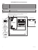
Switch Position:
24VDC = SW1 OPEN
12VDC = SW1 CLOSED
OFF ON
Power ON/OFF
Switch
Trimpot
Wire Strap
(
from
Enclosure
t
o Door)
Used on PTC Models
(example: ALTV1224DCCB)
24V - OPEN
12V - CLOSED
24V - OPEN
12V - CLOSED
Fig. 1
Fig. 1A
Fig. 1B
Fig. 1C
Power Supply
Board