AL842ULADA NAC Power Extender Installation Guide (See Application Guide for additional information) Altronix Corp. 140 58th St. Brooklyn, NY Rev.
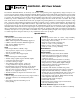
AL842ULADA - NAC Power Extender Overview: The Altronix AL842ULADA is an extremely cost effective 8 amp remote power supply/battery charger. It may be connected to any 24 volt Fire Alarm Control Panel (FACP). Primary applications include Notification Appliance Circuit (NAC such as strobes and horns) expansion support to meet ADA requirements. It also provides auxiliary power to support system accessories.
Power Supply Specifications: AC Input: 120VAC 60Hz, 5 amp supplied by a maximum 15 amp dedicated branch circuit. Output: Four (4) regulated supervised NAC output circuits, 24VDC, 2.5 amp maximum current. One (1) aux. special application 24VDC power output circuit 1 amp, non-supervised total output current must not exceed current 8 amp in Alarm Condition. Battery: Use two (2) 12VDC / 12AH or two (2) 12VDC / 7AH batteries connected in series.
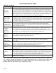
Output Programming Selection Table: Outputs must be programmed independently (OUT1 - OUT4) Function Switch Positions Descriptions ON OFF Input to Output Follower Mode 1 2, 3 Output follows signal it receives from the corresponding input (i.e. FACP Sync module - maintains synchronization of notification appliance circuit). Temporal Code 3 Mode 3 1, 2 Enables Temporal Code 3 signal generation output. This mode will accept a steady or a pulsing input.
Terminal Identification Table: AL842LGK - Logic Board Terminal Legend Function/Description IN1+, IN1IN2+, IN2(Supervised) These terminals connect to the24VDC FACP notification appliance circuit outputs. (Class A, Style Z or Class B, Style W, Y) Input trigger voltage is 8-33VDC @ 5mA min. Terminal polarity is shown in alarm condition. During an alarm condition these inputs will cause the selected outputs chosen to drive notification appliances.
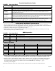
AL800ADA - Power Supply Board Terminal Identification Table: Terminal Legend Function/Description L, G, N Connect 120VAC to these terminals: L to hot, N to neutral. - DC + 24VDC @ 8 amp in alarm non-power limited output. AC FAIL NO, C, NC Form “C” dry contacts indicate the loss of AC, with AC present terminals marked [NO and C] are open, [NC and C] are closed. When loss of AC occurs terminals marked [NO and C] are closed, [NC and C] are open.
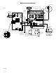
-- RET1 + -- LOOP1 + -- LOOP2 + -- OUT1 + -- OUT2 + -- LOOP3 + -- LOOP4 + -- A -- OUT3 + -- OUT4 + (See Typical Application Diagram for device hookup) C "FAULT" NC Fig. 2a Addressable control module trigger output Addressable control module trigger output Fig.
Optional hookups: 1- Battery and AC monitoring: AC or Battery Fail condition will cause the common trouble input [C “FAULT” NC] to report back to the FACP via input 1 and input 2. The common trouble input may also be used for other optional supervisory monitoring. To report AC and Battery Trouble connect the battery and AC Fail relay output shown in (Fig. 2a) to the common trouble input.
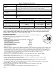
Battery Calculation Worksheet Device For each device use this formula: Number of Current per Device Devices This column x This column = Equals AL842ULADA (Current draw from battery) 1 A AL842 Current Auxiliary Devices Stand-by: 90mA Alarm: 175mA 90mA 175mA 90mA 175mA Refer to device manual for current ratings. Alarm/Stand-by Alarm/Stand-by Alarm/Stand-by B Stand-by Alarm Current Current Current per number of devices.
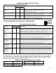
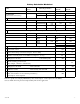
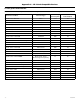
Appendix A - UL Listed Compatible Devices A.1 Four (4) Wire Smoke Detectors Table A-1 below lists four (4) wire smoke detectors compatible with AL842ULADA AUX output. Base Max Standby Current (mA) 0.12 Alarm Current (mA) 36 System Sensor B114LP Base * * System Sensor B404B Base * * System Sensor DH100ACDC Photoelectric 0.15 0.70 System Sensor DH100ACDCLP Photoelectric 0.15 0.70 System Sensor DH100ACDCLPW Photoelectric 0.15 0.
A.1 Four (4) Wire Smoke Detectors (cont.) Detector Type Smoke Detector/Base Max Standby Current (mA) .05 .05 .05 .05 Alarm Current (mA) 23 23 35 35 System Sensor 4W-B (12/24 volt) System Sensor 4WT-B (12/24 volt) System Sensor 4WTA-B (12/24 volt) System Sensor 4WTR-B (12/24 volt) Photoelectric I3 Photoelectric I3 w/Therm I3 Photo w/Therm/Sounder I3 Photo w/Therm/Relay System Sensor 4WTR-B (12/24 volt) I3 Photo w/Therm/ Sounder/Relay .05 50 I3 Photo w/Isolated Therm/ Sounder/Relay .
Enclosure Dimensions (H x W x D approximate): 18” x 14.5” x 4.625” (457.2mm x 368.3mm x 117.48mm) 14.5” (368.3mm) 1.5” (38.1mm) 2.5” (63.5mm) 2.5” (63.5mm) 1.5” (38.1mm) 4.5” (114.3mm) 1.0” (25.4mm) 1.25” (31.75mm) 1.5” (38.1mm) 1.25” (31.75mm) 1.5” (38.1mm) 1.0” (25.4mm) 1.0” (25.4mm) 1.5” (38.1mm) 2.5” (63.5mm) 8.5” (215.9mm) 6.0” (152.4mm) 18.0” (457.2mm) 18.0” (457.2mm) 18.0” (457.2mm) 1.0” (25.4mm) 1.0” (25.4mm) 1.0” (25.4mm) 2.75” (69.85mm) 1.5” (38.1mm) 14.5” (368.3mm) 4.