
Installation Guide

AL842ULADA - 5 -
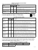
*Not to exceed a maximum of 2.5 amp per NAC.
Terminal Identification Table:
AL842LGK - Logic Board
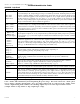
Terminal Legend Function/Description
IN1+,IN1-
IN2+,IN2-
(Supervised)
Theseterminalsconnecttothe24VDCFACPnotificationappliancecircuitoutputs.(ClassA,Style
ZorClassB,StyleW,Y)Inputtriggervoltageis8-33VDC@5mAmin.Terminalpolarityisshown
inalarmcondition.Duringanalarmconditiontheseinputswillcausetheselectedoutputschosen
todrivenotificationappliances.Thedesignatedoutputsaresetbyoutputswitches[OUT1through
OUT4] (Output Programming Selection Table, pg. 4). A troublcondition on an output loop will
causethecorrespondinginputtotriptheFACPbyopeningtheFACPloop.Analarmconditionwill
alwaysoverridetroubletodrivenotificationappliances.
RET1+,RET1-
RET2+,RET2-
(Supervised)
ForClassA,StyleZhookupstheseterminalpairsreturntoFACPNAC1and/orNAC2.
ForClassB,StyleW,YhookupstheFACPEOLresistorfromtheNAC1and/orNAC2outputsare
terminatedattheseterminals.Optionally,othernotificationappliancesoradditionalsignalingcircuit
powersuppliesmaybeconnectedtotheseterminals.IfthisoptionischosentheEOLresistormust
beterminatedatthelastdevice.
C“DRY1”NC
C“DRY2”NC
(Dryinputtrigger)
Anopenacrosstheseinputs,willcausetheselectedoutputschosentodrivenotificationappliances.
Thedesignated outputs areset by outputswitches [OUT1 throughOUT4](Output Programming
Selection Table, pg. 4).Notetheseinputsareunidirectionalandwillnotreportatroublecondition
totheFACP.
+OUT1--
+OUT2--
+OUT3--
+OUT4--
(Supervised)
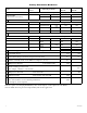
Notificationappliancesareconnectedtotheseregulatedoutputs(see Application Guide, pgs. 2-4).
Each power-limited output will supply 2 amp. Total supply current is 8 amp (see note below).
Outputsarecontrolledbydesignatedinput1[IN1]orinput2[IN2] (Output Programming Selection
Table, pg. 4).Maximumlinelossorvoltagedrop(testedwith2.5V).
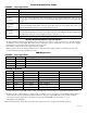
+Loop1--
+Loop2--
+Loop3--
+Loop4--
UsedforClassA,StyleZhook-upstoterminateloopsoriginatingon
[OUT1],[OUT2],[OUT3],and[OUT4]respectively.
C“FAULT”NC
(Common
troubleinput)
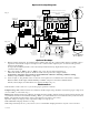
Anopencircuitacrossthispairofterminalswillcause[INP1andINP2]LEDstosimultaneously
signalatroubleconditionbacktotheFACP(TypicallyusedtoreportACorBATFail).
(Fig. 2e, pg. 7).
NC,C,NO
(Common
troubleoutput)
Thesearedrycontacttroubleoutputsthatreportanygeneralloop/systemtroubleconditions.
(Typicallyusedtotriggeradigitalcommunicatororotherreportingdevices).
(form“C”contact1amp/28VDC0.35PowerFactor)(Fig. 2, pg. 7).
--AUX+
This separate 1 amp max. auxiliary special application power output circuit is typically used to
powerelectromagneticdoorholdersthatkeepfireandsmokedoorsopenundernormalconditions.
--AUX2+
This separate auxiliary regulated power output circuit supplies up to 1 amp during stand-by and
alarm condition to auxiliary special application power output circuit is typically used to power
4-wiresmokedetectors.Seeattachedlistofdevices(Appendix A, pgs. 9-11).Sincethisoutputisnot
disconnectedfromitsloadduringACpowerfailureusethe(Battery Calculation Worksheet, pg. 8)
todeterminebatterysizeand/orallowablestand-byandalarmcurrent.
+DC-- 24VDCfrompowersupply.
Note: Unit is equipped with two (2) 1 amp max. auxiliary outputs: “AUX1” will automatically disconnect when AC
is lost. “AUX2” will remain battery backed up during the power outage. For loads connected to “AUX2” please
refer to battery “Stand-by Specifications” above for ratings. When loads are connected to the “AUX1” and/or
“AUX2” outputs during alarm condition, the remaining outputs may not exceed 8 amp total alarm current.
(example: AUX1 = 1 amp, AUX2 = 1 amp, outputs up to 7 amp).