AL802ULADAJ NAC Power Extender Installation Guide (See Application Guide for additional information) Rev.
AL802ULADAJ - NAC Power Extender Overview: The Altronix AL802ULADAJ is an extremely cost effective 8 amp remote power supply/battery charger. It may be connected to any 12 or 24 volt Fire Alarm Control Panel (FACP). Primary applications include Notification Appliance Circuit (NAC such as strobes and horns) expansion support to meet ADA requirements. It also provides auxiliary power to support system accessories.
Power Supply Specifications: AC Input: 120VAC 60Hz, 5 amp, supplied by a maximum 15 amp dedicated branch circuit. Output: Four (4) regulated supervised NAC output circuits, 24VDC, 2.5 amp maximum current. One (1) aux. special application 24VDC power output circuit 1 amp, non-supervised total output current must not exceed current 8 amp in Alarm Condition. Battery: Use two (2) 12VDC / 12AH or two (2) 12VDC / 7AH batteries connected in series.
Note: The 2-wire horn/strobe sync mode will only synchronize horns, horn/strobes, strobes with synchronization capability. 7. For connection of smoke detectors, digital dialer (Optional Hookup Diagram, pg. 7). Class A, Style Z Class B, Style W, Y, SW1 & SW2 Settings: • For all Class B, Style W, Y, hookups SW1 & SW2 on the AL800LGK logic board must be open. For all Class A, Style Z hookups SW1 & SW2 on the AL800LGK logic board must be closed.
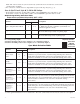
Note: It is required to control visual notification appliances (strobes) via input 1 [IN1] and audible notification appliances (horns) via input 2 [IN2]. This allows audible notification appliances (horns) to be silenced while visual notification appliances (strobes) continue to operate. Amount of Notification Appliances per unit: Amseco Faraday Gentex® 27 per NAC* 39 per NAC* 32 per NAC* System Sensor® CooperWheelock® 32 per NAC* 32 per NAC* *Not to exceed a maximum of 2.
Terminal Identification Table: AL800ADA Power Supply Board* Terminal Legend Function/Description L, G, N Connect 120 VAC to these terminals: L to hot, N to neutral, G to ground. + DC – 24VDC @ 8 amp in alarm non-power limited output. Form “C” dry contacts used to instantaneously signal the loss AC to local annunciation devices, with AC present terminals marked NO and C are open, NC and C are closed. When loss of AC occurs terminals marked NO and C are closed, NC and C are open.
* Indicates current trouble condition. When trouble (open, short or ground) occurs on a specific output, the corresponding red output LED, [OUT1-OUT4] will blink. The corresponding green input LED will blink as well. Loop trouble will report within 30 seconds. ** Indicates trouble condition memory. When a trouble condition restores, the units red output LED, [OUT1-OUT4] will blink with a shorter and distinctly a different duration. The green input LEDs will be off (normal condition).
Optional hookups: 1- Battery and AC monitoring: AC or Battery Fail condition will cause the common trouble input [C “FAULT” NC] to report back to the FACP via input 1 and input 2. The common trouble input may also be used for other optional supervisory monitoring. To report AC and Battery Trouble connect the battery and AC Fail relay output shown in (Fig. 2a) to the common trouble input.
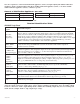
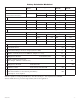
Battery Calculation Worksheet Device Number of Devices For each device use this formula: This column x This column = AL802ULADAJ (Current draw from battery) 1 A AL802 Current Auxiliary Devices B Stand-by Current Current per Device Equals Stand-by: 90mA Alarm: 175mA Alarm Current Current per number of devices. 90mA 175mA 90mA 175mA Refer to device manual for current ratings.
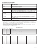
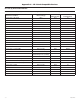
Appendix A - UL Listed Compatible Devices A.1 Four (4) Wire Smoke Detectors Table A-1 below lists four (4) wire smoke detectors compatible with AL802ULADAJ AUX output.
A.1 Four (4) Wire Smoke Detectors (cont.) Detector Type Smoke Detector/Base Max Standby Current (mA) .05 .05 .05 .05 Alarm Current (mA) 23 23 35 35 System Sensor 4W-B (12/24 volt) System Sensor 4WT-B (12/24 volt) System Sensor 4WTA-B (12/24 volt) System Sensor 4WTR-B (12/24 volt) Photoelectric I3 Photoelectric I3 w/Therm I3 Photo w/Therm/Sounder I3 Photo w/Therm/Relay System Sensor 4WTR-B (12/24 volt) I3 Photo w/Therm/ Sounder/Relay .05 50 I3 Photo w/Isolated Therm/Sounder/Relay .
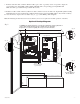
Enclosure Dimensions: 18"H x 14.5"W x 4.5"D 14.50" 1.50" 1.25" 1.50" 2.50" 2.50" 1.50" 1.50" 1.00" 1.00" 1.25" 1.00" 1.50" 2.50" 8.50" 6.00" 18.00" 18.00" 1.00" 18.00" 1.00" 1.50" 1.00" 14.50" 2.75" 4.50" 4.50" 2.75" Altronix is not responsible for any typographical errors. 140 58th Street, Brooklyn, New York 11220 USA, 718-567-8181, fax: 718-567-9056 web site: www.altronix.com, e-mail: info@altronix.com, Lifetime Warranty, Made in U.S.A.