
Installation Instructions Instruction Manual

AL802ULADA - 7 -
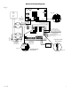
These circuits are used to
monitor AC and Bat Fail and
will cause a simultaneous trouble
condition to the FACP's IN1 and IN2
Digital Communicator or
Local Annunciator Dry output Contact
(Form "C" contacts)
4-wire Smoke
Detector
+
--
+
--
4-wire Smoke
Detector
Fire
Alarm
Control
Panel
(FACP)
EOL Power
Supervision Relay
(Not Supplied)
EOL
Resistor
from
FACP
SW1
-- DC +
SW2
+ OUT1 --
OUT1 OUT2 OUT3 OUT4
INP1 INP2
FAULT
NC CNOC "FAULT" NC
OUT1 OUT3
OUT2 OUT4
INPUT SELECT
TEMPORAL
STROBE SYNC
IN > OUT SYNC
IN1+
IN1--
IN2--
IN2+
C "DRY1" NC
RET1+
RET1--
RET2--
RET2+
C "DRY2" NC
+ OUT2 --
+ OUT3 --
+ OUT4 --
INPUT SELECT
TEMPORAL
STROBE SYNC
IN > OUT SYNC
-- AUX +
UPPER TERMINALS
LOWER TERMINALS
Addressable
Control Module
Trigger Output
See Note 2
line
ground
neutral
GreenLead
Use separate knockout.
Keep 1/4" spacing from
non power limited wiring
Power-LimitedOutputs
2.5ampper
outputinalarm
(total=8amp)
(Supervised)
Supervised Non-Supervised
Non-Supervised
Non-Supervised
RESET
unswitched 120VAC
power mains
(non-power limited)
NC C NO
NC C NO NC C NO
AC Local
AC DELAY
BAT FAIL AC FAIL
AC LED
VR1
Fig. 2
These circuits are used to
monitor AC and Bat Fail and
will cause a simultaneous trouble
condition to the FACP's IN1 and IN2
Digital Communicator or
Local Annunciator Dry output Contact
(Form "C" contacts)
4-wire Smoke
Detector
+
--
+
--
4-wire Smoke
Detector
Fire
Alarm
Control
Panel
(FACP)
EOL Power
Supervision Relay
(Not Supplied)
EOL
Resistor
from
FACP
SW1
-- DC +
SW2
+ OUT1 --
OUT1 OUT2 OUT3 OUT4
INP1 INP2
FAULT
NC CNOC "FAULT" NC
OUT1 OUT3
OUT2 OUT4
INPUT SELECT
TEMPORAL
STROBE SYNC
IN > OUT SYNC
IN1+
IN1--
IN2--
IN2+
C "DRY1" NC
RET1+
RET1--
RET2--
RET2+
C "DRY2" NC
+ OUT2 --
+ OUT3 --
+ OUT4 --
INPUT SELECT
TEMPORAL
STROBE SYNC
IN > OUT SYNC
-- AUX +
UPPER TERMINALS
LOWER TERMINALS
Addressable
Control Module
Trigger Output
See Note 2
line
ground
neutral
GreenLead
Use separate knockout.
Keep 1/4" spacing from
non power limited wiring
Power-LimitedOutputs
2.5ampper
outputinalarm
(total=8amp)
(Supervised)
Supervised Non-Supervised
Non-Supervised
Non-Supervised
RESET
unswitched 120VAC
power mains
(non-power limited)
NC C NO
NC C NO NC C NO
AC Local
AC DELAY
BAT FAIL AC FAIL
AC LED
VR1
NC CNOC "FAULT" NC
Fig. 2b
Fig. 2a
These circuits are used to
monitor AC and Bat Fail and
will cause a simultaneous trouble
condition to the FACP's IN1 and IN2
Digital Communicator or
Local Annunciator Dry output Contact
(Form "C" contacts)
4-wire Smoke
Detector
+
--
+
--
4-wire Smoke
Detector
Fire
Alarm
Control
Panel
(FACP)
EOL Power
Supervision Relay
(Not Supplied)
EOL
Resistor
from
FACP
SW1
-- DC +
SW2
+ OUT1 --
OUT1 OUT2 OUT3 OUT4
INP1 INP2
FAULT
NC CNOC "FAULT" NC
OUT1 OUT3
OUT2 OUT4
INPUT SELECT
TEMPORAL
STROBE SYNC
IN > OUT SYNC
IN1+
IN1--
IN2--
IN2+
C "DRY1" NC
RET1+
RET1--
RET2--
RET2+
C "DRY2" NC
+ OUT2 --
+ OUT3 --
+ OUT4 --
INPUT SELECT
TEMPORAL
STROBE SYNC
IN > OUT SYNC
-- AUX +
UPPER TERMINALS
LOWER TERMINALS
Addressable
Control Module
Trigger Output
See Note 2
line
ground
neutral
GreenLead
Use separate knockout.
Keep 1/4" spacing from
non power limited wiring
Power-LimitedOutputs
2.5ampper
outputinalarm
(total=8amp)
(Supervised)
Supervised Non-Supervised
Non-Supervised
Non-Supervised
RESET
unswitched 120VAC
power mains
(non-power limited)
NC C NO
NC C NO NC C NO
AC Local
AC DELAY
BAT FAIL AC FAIL
AC LED
VR1
Fig. 2c
TroubleMemory
ResetButton
Commontrouble
Input/Output
Optional Hookup Diagram: