
Installation Guide

AL802ULADA - 7 -
These circuits are used to
monitor AC and Bat Fail and
will cause a simultaneous trouble
condition to the FACP's IN1 and IN2
Digital Communicator or
Local Annunciator Dry output Contact
(Form "C" contacts)
4-wire Smoke
Detector
+
--
+
--
4-wire Smoke
Detector
Fire
Alarm
Control
Panel
(FACP)
EOL Power
Supervision Relay
(Not Supplied)
EOL
Resistor
from
FACP
SW1
-- DC +
SW2
+ OUT1 --
OUT1 OUT2 OUT3 OUT4
INP1 INP2
FAULT
NC CNOC "FAULT" NC
OUT1 OUT3
OUT2 OUT4
INPUT SELECT
TEMPORAL
STROBE SYNC
IN > OUT SYNC
IN1+
IN1--
IN2--
IN2+
C "DRY1" NC
RET1+
RET1--
RET2--
RET2+
C "DRY2" NC
+ OUT2 --
+ OUT3 --
+ OUT4 --
INPUT SELECT
TEMPORAL
STROBE SYNC
IN > OUT SYNC
-- AUX +
UPPER TERMINALS
LOWER TERMINALS
Addressable
Control Module
Trigger Output
See Note 2
line
neutral
Use separate knockout.
Keep 0.25" spacing from
non power-limited wiring
Power-Limited Outputs
2.5 amp per
output in alarm
(total= 8 amp)
(Supervised)
Supervised Non-Supervised
Non-Supervised
Non-Supervised
RESET
unswitched 120VAC
power mains
(non power-limited)
NC C NO
NC C NO NC C NO
AC Local
AC DELAY
BAT FAIL AC FAIL
AC LED
VR1
Fig. 2
These circuits are used to
monitor AC and Bat Fail and
will cause a simultaneous trouble
condition to the FACP's IN1 and IN2
Digital Communicator or
Local Annunciator Dry output Contact
(Form "C" contacts)
4-wire Smoke
Detector
+
--
+
--
4-wire Smoke
Detector
Fire
Alarm
Control
Panel
(FACP)
EOL Power
Supervision Relay
(Not Supplied)
EOL
Resistor
from
FACP
SW1
-- DC +
SW2
+ OUT1 --
OUT1 OUT2 OUT3 OUT4
INP1 INP2
FAULT
NC CNOC "FAULT" NC
OUT1 OUT3
OUT2 OUT4
INPUT SELECT
TEMPORAL
STROBE SYNC
IN > OUT SYNC
IN1+
IN1--
IN2--
IN2+
C "DRY1" NC
RET1+
RET1--
RET2--
RET2+
C "DRY2" NC
+ OUT2 --
+ OUT3 --
+ OUT4 --
INPUT SELECT
TEMPORAL
STROBE SYNC
IN > OUT SYNC
-- AUX +
UPPER TERMINALS
LOWER TERMINALS
Addressable
Control Module
Trigger Output
See Note 2
line
neutral
Use separate knockout.
Keep 0.25" spacing from
non power-limited wiring
Power-Limited Outputs
2.5 amp per
output in alarm
(total= 8 amp)
(Supervised)
Supervised Non-Supervised
Non-Supervised
Non-Supervised
RESET
unswitched 120VAC
power mains
(non power-limited)
NC C NO
NC C NO NC C NO
AC Local
AC DELAY
BAT FAIL AC FAIL
AC LED
VR1
NC CNOC "FAULT" NC
Fig. 2b
Fig. 2a
These circuits are used to
monitor AC and Bat Fail and
will cause a simultaneous trouble
condition to the FACP's IN1 and IN2
Digital Communicator or
Local Annunciator Dry output Contact
(Form "C" contacts)
4-wire Smoke
Detector
+
--
+
--
4-wire Smoke
Detector
Fire
Alarm
Control
Panel
(FACP)
EOL Power
Supervision Relay
(Not Supplied)
EOL
Resistor
from
FACP
SW1
-- DC +
SW2
+ OUT1 --
OUT1 OUT2 OUT3 OUT4
INP1 INP2
FAULT
NC CNOC "FAULT" NC
OUT1 OUT3
OUT2 OUT4
INPUT SELECT
TEMPORAL
STROBE SYNC
IN > OUT SYNC
IN1+
IN1--
IN2--
IN2+
C "DRY1" NC
RET1+
RET1--
RET2--
RET2+
C "DRY2" NC
+ OUT2 --
+ OUT3 --
+ OUT4 --
INPUT SELECT
TEMPORAL
STROBE SYNC
IN > OUT SYNC
-- AUX +
UPPER TERMINALS
LOWER TERMINALS
Addressable
Control Module
Trigger Output
See Note 2
line
neutral
Use separate knockout.
Keep 0.25" spacing from
non power-limited wiring
Power-Limited Outputs
2.5 amp per
output in alarm
(total= 8 amp)
(Supervised)
Supervised Non-Supervised
Non-Supervised
Non-Supervised
RESET
unswitched 120VAC
power mains
(non power-limited)
NC C NO
NC C NO NC C NO
AC Local
AC DELAY
BAT FAIL AC FAIL
AC LED
VR1
Fig. 2c
Trouble Memory
Reset Button
Common trouble
Input/Output
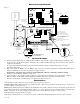
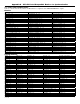
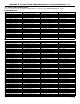
Optional Hookup Diagram:
Optional Hookups:
1- Battery and AC monitoring: AC or Battery Fail condition will cause the common trouble input [C “FAULT” NC]
to report back to the FACP via input 1 and input 2. The common trouble input may also be used for other optional
supervisory monitoring.
To report AC and Battery Trouble connect the battery and AC Fail relay output shown in (Fig. 2a) to the
common trouble input.
2- Dry contact input (C “DRY1” NC) (C “DRY2” NC) can be used to alarm output from an addressable module (these
inputs are unidirection and cannot report back to trigger module).
Connection to triggering devices must be made within 20ft of distance and using conduit for wiring.
3- Auxiliary output (-AUX+) 24VDC at 1 amp max.
4- AC Local [NC, C, NO ] should connect to the host control panel for local annunciation of the trouble condition.
Note: If common trouble input, terminals marked [C “FAULT” NC] are not used, these terminals must be
shorted (connect jumper) to remain inactive. For optional hookups see Fig. 2b.
Maintenance:
Unit should be tested at least once a year for the proper operation as follows:
Output Voltage Test: Under normal load conditions the DC output voltage should be checked for proper voltage level
(26.2-26.4VDC recommended range).
Battery Test: Under normal load conditions check that the battery is fully charged. Check specified voltage both at the bat-
tery terminal and at the board terminals marked [+ BAT -- ] to ensure that there is no break in the battery connection wires.
Fuses: Check fuse on the power supply board, replace if necessary. Input fuse rating is 5 amp @ 250V.
Note: Maximum charging current is 3.2 amp.
Note: Expected battery life is 5 years; however, it is recommended changing batteries in 4 years or less if needed.