
Installation Guide
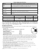
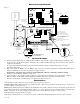


AL802ULADA - 11 -
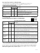
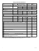
Appendix A - UL/cUL Listed Compatible Devices for Synchronization (cont’d)
A-1 Strobes, Horns and Horn/Strobes
Table A-1 below lists Strobes, Horns and Horn/Strobes compatible with AL802ULADA NAC outputs.
Cooper/Wheelock:
S8-24MCCH-FW - UL/cUL STH-3R24MCCH-NR - UL STR-ALB - UL STW-ALB - UL
SA-S70-24MCW-FR - UL STH-4M30WC - UL STR-NA - UL STW-NA - UL
SA-S70-24MCW-FW - UL STH-4MS-R - UL STR-NB - UL STW-NB - UL
SA-S90-24MCC-FR - UL STH-4R - UL STR-NG - UL STW-NG - UL
SA-S90-24MCC-FW - UL STH-4R24MCCH-NW - UL STR-NR - UL STW-NR - UL
STH-2G - UL STH-4R24MCCH110B-NR - UL STRC-NA - UL STWC-AB - UL
STH-2MS-R - UL STH-4R24MCCH110R-NA - UL STRC-NB - UL STWC-ALA - UL
STH-2R - UL STH-4R24MCCH110R-NR - UL STRC-NG - UL STWC-ALB - UL
STH-2R24MCCH-NR - UL STH-90-4R24MCCH-NW - UL STRC-NR - UL STWC-NA - UL
STH-3MS-R - UL STR-AB - UL STW-AB - UL STWC-NB - UL
STH-3R - UL STR-ALA - UL STW-ALA - UL STWC-NG - UL
STWC-NR - UL
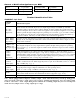
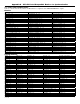
Appendix B - UL Listed Compatible Devices
B.1 Four (4) Wire Smoke Detectors
Table B-1 below lists four (4) wire smoke detectors compatible with AL802ULADA AUX output and Outputs 1-8 when
programmed as AUX.
System Sensor
Smoke Detector/Base
Detector Type
Max Stand-by
Current (mA)
Alarm
Current (mA)
B112LP Base 0.12 36
B114LP Base * *
B404B Base * *
DH100ACDC Photoelectric 0.15 0.70
DH100ACDCLP Photoelectric 0.15 0.70
DH100ACDCLPW Photoelectric 0.15 0.70
DH400ACDCI Ionization Duct 25 95
DH400ACDCP Photoelectric Duct 25 95
1112/24/D Ionization 0.05 50
1424 Ionization 0.10 41
1451 (w/B402B Base) Ionization 0.10 39
2112/24ATR Photoelectric 0.50 60/70
2112/24AITR Photoelectric 0.50 60/70
2112/24/D Photoelectric 0.05 50
2112/24R Photoelectric 0.50 60/70
2112/24TR Photoelectric 0.50 60/70
2112/24T/D Photoelectric w/135
o
Thermal 0.05 50
2112/24TSRB Photoelectric w/135
o
Thermal Supervisory Relay 15 45
2312/24TB Photoelectric 0.12 50
2412 (12 volt) Photoelectric 0.12 77
2412AT (12 volt) Photoelectric 0.12 58
2412TH (12 volt) Photoelectric 0.12 77
2424 Photoelectric 0.10 41
2424TH Photoelectric 0.10 41
2451 Photoelectric 0.10 39
2451TH (with/B402B Base) Photoelectric 0.10 39
2W-MOD Loop Test/Maintenance Mod. 30 50
4W-B (12/24 volt) Photoelectric I
3
0.05 23
4WT-B (12/24 volt) Photoelectric I
3
w/Therm 0.05 23
4WTA-B (12/24 volt) I
3
Photo w/Therm/Sounder 0.05 35
4WTR-B (12/24 volt) I
3
Photo w/Therm/Relay 0.05 35
4WTR-B (12/24 volt) I
3
Photo w/Therm/Sounder/Relay 0.05 50
4WITAR-B (12/24 volt) I
3
Photo w/Isolated Therm/Sounder/Relay 0.05 50
2W-MOD2 I
3
Loop Test/Maintenance Mod. 0.05 *
RRS-MOD I
3
Reversing Relay/Sync Module 0.05 *
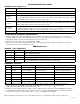
6424 Projected Beam 10 28.4
Beam 1224(S) Projected Beam 17 38.5
* Contact manufacturer for current draws.
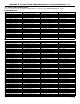
B.2 Relays
Table B-3 below lists relays compatible with AL802ULADA AUX output and Outputs 1-8 when programmed as AUX.
Manufacturer Model Current (mA) Manufacturer Model Current (mA) Manufacturer
System
Sensor
PR-1 15
System
Sensor
R-10T 23
System
Sensor
R-10E 23
PR-2 30 R-14T 23 R-14E 23
PR-3 30 R-20T 40 R-20E 40
EOLR-1 30 R-24T 40 R-24E 40