
Installation Instructions

LED Diagnostics:
Red (DC) Green (AC) Power Supply Status
ON ON Normal operating conditions
ON OFF Loss of AC. Stand-by battery is supplying power.
OFF ON No DC output. Short circuit or thermal overload condition.
OFF OFF No DC output. Loss of AC. Discharged or no battery present.
Terminal Identification:
Terminal Legend Function/Description
AC/AC Low voltage AC input (Voltage Output/Transformer Selection Table, pg.1).
+ DC – 6VDC or 12VDC @ 1.2A continuous supply current.
– BAT + Stand-by battery connections. Maximum charge rate 300mA.
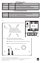
Fig. 1a
Nylon Fastener
STEP 2: Mount AL624 circuit board to nylon fasteners
by pressing down circuit board onto nylon fasteners.
Note: Springlock on fasteners is used to remove AL624 circuit board.
Note: Four (4) fasteners are provided in the AL624 carton.
Springlock
Fig. 1
AC AC +DC -BAT +
AC
DC
FACTORY SET AT 12V
CUT J1 FOR 24V
CUT J2 FOR 6V
J1
J2
STEP 1: Use these holes to mount
AL624 by pushing the nylon
circuit board fasteners (Fig. 1a)
through the back of the enclosure.
Nylon fasteners will snap into place.
Altronix is not responsible for any typographical errors.
––––––––––––––––––––––––––––––––––––––––––––––––––––––––––––––––––––––––––––––––––––––––––––––––––––––––––––––––
140 58th Street, Brooklyn, New York 11220 USA | phone: 718-567-8181 | fax: 718-567-9056
website: www.altronix.com | e-mail: info@altronix.com | Lifetime Warranty
IIAL624ET - Rev. 110599 F21U
MEMBER