AL602ULADA NAC Power Extender Installation Guide (see 02 Application Guide for additional information) Altronix Corp. 140 58th St. Brooklyn, NY Rev.
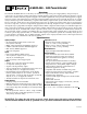
AL602ULADA - NAC Power Extender Overview: The Altronix AL602ULADA is an extremely cost effective 6.5 amp remote power supply/battery charger. It may be connected to any 24 volt Fire Alarm Control Panel (FACP). Primary applications include Notification Appliance Circuit (NAC such as strobes and horns) expansion support to meet ADA requirements. It also provides auxiliary power to support system accessories.
Power Supply Specifications: AC Input: 120VAC 60Hz, 4 amp. Output: Four (4) regulated supervised NAC output circuits, 24VDC, 2.5 amp maximum current. One (1) aux. special application 24VDC power output circuit 1 amp, non-supervised total output current must not exceed current 6.5 amp in Alarm Condition. Battery Use two (2) 12VDC / 7AH, two (2) 12VDC / 12AH or two (2) 12VDC / 40AH batteries connected in series. Stand-by/Alarm Current Consumption: 90mA/175mA EOL Resistor (end of line): 2.
Note: The 2-wire horn/strobe sync mode will only synchronize horns, horn/strobes, strobes with synchronization capability. 7. For connection of smoke detectors, digital dialer (see Hookup Diagram, pg. 7). Class A, Style Z Class B, Style W, X, Y, SW1 & SW2 Settings: • For all Class B, Style W, X, Y, hookups SW1 & SW2 on the AL800LGK9E logic board must be open. For all Class A, Style Z hookups SW1 & SW2 on the AL800LGK9E logic board must be closed.
*Note: The AL602ULADA will only synchronize horns, horn/strobes and strobes that contain synchronization capability. Contact signal manufacturer for more detailed info (see Appendix A.4, pg. 12). The same synchronization mode must be selected for all outputs Amount of Notification Appliances per NAC: Amseco 27 per NAC* System Sensor® Faraday 39 per NAC* CooperWheelock® Gentex® 32 per NAC* 32 per NAC* 32 per NAC* *Not to exceed a maximum of 2.5 amp per NAC.
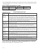
AL600ADA Power Supply Board* Terminal Identification Table: Terminal Legend Function/Description L, G, N Connect 120 VAC to these terminals: L to hot, N to neutral. - DC + 24VDC @ 6.5 amp in alarm non power-limited output. AC FAIL NO, C, NC Form “C” dry contacts used to instantaneously signal the loss AC to local annunciation devices, with AC present terminals marked NO and C are open, NC and C are closed. When loss of AC occurs terminals marked NO and C are closed, NC and C are open.
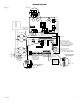
No Supervised Non-power limited Hookup Diagram: Fig. 2 tched 120VAC wer mains power limited) Fig. 2a 5A AC Local Use separate knockout. Keep 1/4" spacing from non power limited wiring Divider Green Lead OUT1 OUT3 INPUT SELECT TEMPORAL STROBE SYNC AC FAIL IN > OUT SYNC OUT25A OUT4 250V SELECT INPUT TEMPORAL STROBE SYNC IN > OUT SYNC Green Lead line ground neutral RESET + 4-wire Smoke Detector AC Local Use separate knockout.
Optional hookups: 1- Battery and AC monitoring: AC or Battery Fail condition will cause the common trouble input [C “FAULT” NC] to report back to the FACP via input 1 and input 2. The common trouble input may also be used for other optional supervisory monitoring. (see Power Board Parameter for use of AC Delay, pg. 6) To report AC and Battery Trouble connect the battery and AC Fail relay output shown in (Fig. 2a) to the common trouble input.
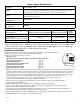
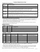
Battery Calculation Worksheet Device For each device use this formula: Number of Current per Device Devices This column x This column = Equals AL602ULADA (Current draw from battery) 1 A AL602 Current Auxiliary Devices Stand-by: 90mA Alarm: 175mA 90mA 175mA 90mA 175mA Refer to device manual for current ratings. Alarm/Stand-by Alarm/Stand-by Alarm/Stand-by B Stand-by Alarm Current Current Current per number of devices.
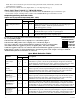
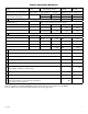
Appendix A - UL Listed Compatible Devices A.1 Four (4) Wire Smoke Detectors Table A-1 below lists four (4) wire smoke detectors compatible with AL602ULADA AUX output.
A.1 Four (4) Wire Smoke Detectors (cont.) Detector Type Smoke Detector/Base Max Standby Current (mA) .05 .05 .05 .05 Alarm Current (mA) 23 23 35 35 System Sensor 4W-B (12/24 volt) System Sensor 4WT-B (12/24 volt) System Sensor 4WTA-B (12/24 volt) System Sensor 4WTR-B (12/24 volt) Photoelectric I3 Photoelectric I3 w/Therm I3 Photo w/Therm/Sounder I3 Photo w/Therm/Relay System Sensor 4WTR-B (12/24 volt) I3 Photo w/Therm/ Sounder/Relay .
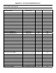
A.4 Strobes Table A-4 below lists strobes compatible with AL602ULADA NAC output.
A.4 Strobes (cont.) Wheelock Devices: Coded Audible Appliances AMT - 12/24 AMT - 12/24-NYC CH70 CSX10-24-DC MT-12/24 AMT4 - 12/24 AMT4 - 12/24-NYC CH90 CSXG10-24-DC MT4-12/24 Non-Synchronizing Appliances MB-G6-12 MB-G10-12 MIZ-TC12 MB-G6-24 MB-G10-24 MIZ-TC24 Gentex Devices: Models GE3 Series SSPK Wall and Ceiling Mount Series GES/GEC Series GCS/ GX93 Series GCC Series WGE and color lense units.
A.4 Strobes (cont.
Notes: AL602ULADA - 15 -
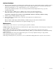
Enclosure Dimensions: 15.5” x 12” x 4.5” (393.7mm x 304.8mm x 114.3mm) 1.5” (38.1mm) 4.615” (117.22mm) 4.615” (117.22mm) 1.5” (38.1mm) 1.75” (44.45mm) 1.375” (34.925mm) 1.125” (28.575mm) 1.25” (31.75mm) 4.5” (114.3mm) 12.23” (310.64mm) 1.1” (27.94mm) 0.91” (23.114mm) 1.5” (38.1mm) 4.5” (114.3mm) 1.1” (27.94mm) 1.25” (31.75mm) 0.91” (23.114mm) 2.0” (50.8mm) 1.5” (38.1mm) 15.5” (393.7mm) 2.0” (50.8mm) 5.0” (127.0mm) 5.0” (127.0mm) 1.1” (27.94mm) 1.25” (31.75mm) 0.79” (20.06mm) 1.