AL600ULX Series Power Supply/Charger Installation Guide Models Include: • AL600ULX - Single Output • AL600ULPD4 • AL600ULPD4CB - Four (4) Fused Outputs - Four (4) PTC Outputs • AL600ULPD8 • AL600ULPD8CB - Eight (8) Fused Outputs - Eight (8) PTC Outputs • AL600ULXPD16 • AL600ULXPD16CB - Sixteen (16) Fused Outputs - Sixteen (16) PTC Outputs For a red enclosure, add an “R” suffix to the part # e.g. AL600ULPD8R For a larger enclosure, add “XX” to the suffix to the part # e.g. AL600ULXX Rev.
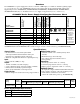
Overview: The AL600ULX is a power supply that converts a 115VAC / 60Hz input, to a 12VDC or 24VDC regulating output (see specifications below). The AL600ULX is the base power supply unit for the UL Listed multi-output power supply/charger series: AL600ULPD4, AL600ULPD4CB, AL600ULPD8, AL600ULPD8CB, AL600ULXPD16, AL600ULXPD16CB (Refer to AL600ULX Series Power Supply Configuration Reference Chart below).
Stand-by Specifications (total current shown): Output 12VDC / 40AH Battery 4 hr. of Stand-by & 5 Minutes of Alarm Stand-by = 6.0 amp Alarm = 6.0 amp 24VDC / 12AH Battery -------- 24VDC / 40AH Battery Stand-by = 6.0 amp Alarm = 6.0 amp 24 hr. of Stand-by & 5 Minutes of Alarm Stand-by = 1.0 amp Alarm = 6.0 amp Stand-by = 200mA Alarm = 6.0 amp Stand-by = 1.0 amp Alarm = 6.0 amp 60 hr. of Stand-by & 5 Minutes of Alarm Stand-by = 300mA Alarm = 6.0 amp -------Stand-by = 300mA Alarm = 6.
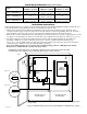
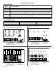
For Fire Alarm applications the outputs are “Special Applications” only, see list (refer to Appendix A, pg. 6). 3. Set the unit to the desired DC output voltage by setting SW1 (Fig. 1b, pg. 3) to the appropriate position (Power Supply Voltage Output Selections Chart, pg. 2). 4. Measure output voltage before connecting any devices to ensure proper operation. Improper or high voltage will damage these devices. When servicing the unit, AC mains should be removed. 5. Connect device(s) to be powered: a.
Terminal Identification: Power Supply Board Terminal Legend L, G, N + DC --- Function/Description Connect 115VAC 60 Hz. to these terminals: L to hot, N to Neutral. 12VDC or 24VDC @ 6 amp continuous npn power-limited output. Indicates loss of AC power, e.g. connect to audible device or alarm panel. Relay normally energized when AC power is present. Contact rating 1 amp @ 28VDC. AC or brownout fail is reported within 1 minute of event. To delay reporting of up to 6 hrs.
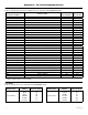
Appendix A - UL Listed Compatible Devices A.1 Four (4) Wire Smoke Detectors Table A-1 below lists four (4) wire smoke detectors compatible with AL600ULX output.
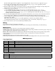
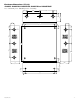
Enclosure Dimensions (BC300): AL600ULX, AL600ULPD4, AL600ULPD4CB, AL600ULPD8 and AL600ULPD8CB 13.5” (342.9mm) x 13” (330.2mm) x 3.25” (82.55mm) 1.40” (36mm) 4.85” (123mm) 4.85” (123mm) 1.40” (36mm) 1.20” (31mm) 3.25” (83mm) 1.20” (31mm) 0.75” (19mm) 12.5” (318mm) 11.0” (279mm) 1.20” (31mm) 0.75” (19mm) 0.9375” (24mm) 1.40” (36mm) 1.40” (36mm) 5.10” (130mm) 5.10” (130mm) 13.0” (330mm) 5.10” (130mm) 6.5625” (167mm) 0.9375” (24mm) 3.25” (83mm) 3.25” (83mm) 3.25” (83mm) 1.0” (25mm) 1.
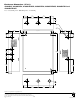
Enclosure Dimensions (BC400): AL600ULXX, AL600ULXPD4, AL600ULXPD4CB, AL600ULXPD8, AL600ULXPD8CB, AL600ULXPD16 and AL600ULXPD16CB 15.5” (393.7mm) x 12” (304.8mm) x 4.5” (114.3mm) 1.5” (38.1mm) 4.615” (117.22mm) 4.615” (117.22mm) 1.5” (38.1mm) 1.75” (44.45mm) 1.375” (34.925mm) 1.125” (28.575mm) 1.25” (31.75mm) 4.5” (114.3mm) 12.23” (310.64mm) 1.1” (27.94mm) 0.91” (23.114mm) 1.5” (38.1mm) 4.5” (114.3mm) 1.1” (27.94mm) 1.25” (31.75mm) 0.91” (23.114mm) 2.0” (50.8mm) 1.5” (38.1mm) 15.5” (393.