
Installation Instructions Owner manual
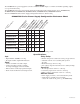

LED Diagnostics:
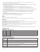
AL400XB220 - Power Supply Board
Terminal Identification:
AL400XB220 - Power Supply Board
AL400X220series - 5 -
Red (DC) Green (AC) Power Supply Status
ON ON Normal operating condition.
ON OFF Loss of
AC, Stand-by battery supplying power.
OFF ON No DC output.
OFF OFF Loss of
A
C. Discharged or no stand-by battery. No Dc output.
Terminal
Legend
Function/Description
L, G, N Connect 220VAC 50/60 Hz. to these terminals: L to hot, N to Neutral, G to ground.
-- DC + 12VDC @ 4 amp or 24VDC @ 3 amp continuous power-limited output.
AC Fail
NC, NC, NO
Indicates loss of AC power, e.g. connect to audible device or alarm panel. Relay normally energized
when AC power is present. Contact rating 1 amp @ 28VDC.
Bat Fail
NC, C, NO
Indicates low battery condition, e.g. connect to alarm panel. Relay normally energized when DC power
is present. Contact rating 1 amp @ 28VDC.
+
B
A
T
--
Stand-b
y batter
y connections. Maximum char
ge cur
rent 1.2 amp.
3
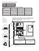
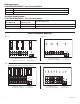
. Set the unit to the desired DC output voltage by setting SW1
(
Fig. 1b, pg. 3)
t
o the appropriate position
(Power Supply Voltage Output Selections Chart, pg. 3).
4
. Measure output voltage before connecting any devices to ensure proper operation. Improper or high voltage will
damage these devices. When servicing the unit, AC mains should be removed.
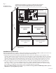
5. Connect devices to be powered:
a. For AL400X220 Power Supply connect devices to terminals marked [- DC +] (
Fig. 1, pg. 3).
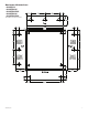
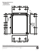
b. For other Power Distribution Models connect devices to be powered to terminal pairs 1 to 4 marked
[1P & 1N thru 4P & 4N] (
Fig. 2a & 2b, pg. 6) or 1 to 8 marked [1P & 1N thru 8P & 8N] (Fig. 3a & 3b, pg. 6)
carefully observing correct polarity.
6. For Access Control applications, batteries are optional. When batteries are not used a loss of AC will result in the
loss of output voltage. When the use of stand-by batteries is desired, they must be lead acid or gel type.
7. Connect appropriate signaling notification devices to AC FAIL & BAT FAIL
(Fig. 1a, pg. 3) supervisory
relay outputs.
Note: When used in fire alarm, burglar alarm or access control applications, “AC Fail” relay should be
utilized to visually indicate that AC power is on
(Fig. 1c, pg. 3).
8. Please insure that the cover is secured with the provided Key Lock.
Wiring:
USE 14 AWG or larger for all power connections.
Note: Take care to keep power-limited circuits separate from non-power limited wiring (220VAC, Battery).
Maintenance:
Unit should be tested at least once a year for the proper operation as follows:
Output Voltage Test: Under normal load conditions, the DC output voltage should be checked for proper voltage level
(Power Supply Voltage Output Specifications Chart, pg. 3).
Battery
Test:
Under nor
mal load conditions check that the battery is fully charged, check specified voltage both at
battery terminal and at the board ter
minals mark
ed [+ BAT -] to insure there is no break in the battery
connection wires.
Note: Maximum charging current under discharges is .7 amp.
Note: Expected batter
y life is 5 years, however it is recommended changing batteries in 4 years or less if needed.