
Installation Instructions Owner manual

- 4 - AL400X220series
Installation Instructions:
W
iring methods shall be in accordance with the National Electrical Code/NFP
A 70/NFP
A 72/ANSI, and with all local
codes and authorities having jurisdiction. Product is intended for indoor use only.
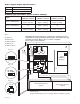
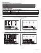
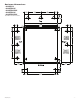
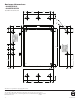
1. Mount unit in desired location. Mark and predrill holes in the wall to line up with the top two keyholes in the
enclosure. Install two upper fasteners and screws in the wall with the screw heads protruding. Place the enclosure’s
upper k
e
yholes over the two upper screws, level and secure. Mark the position of the lower two holes. Remove the
enclosure. Drill the lower holes and install the three fasteners. Place the enclosure’s upper keyholes over the two
upper scre
ws. Install the two lower screws and make sure to tighten all screws
(Enc
losure Dimensions, pg. 7-8).
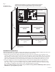
2.
The po
w
er supply is pre-wired to the ground (chassis). Connect main incoming ground to the provided green
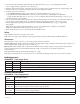
grounding conductor lead. Connect unswitched AC power (220VAC 50/60 Hz to terminals marked [L, G, N]
(Fig. 1, pg. 3 & Fig. 2, pg. 4). Use 14 AWG or larger for all power connections (Battery, DC output, AC input).
Use 22 AWG to 18 AWG for power-limited circuits (AC Fail/Low Battery reporting).
Keep power-limited wiring separate from non power-limited wiring (220VAC 50/60Hz Input, Battery Wires).
Minimum .25” spacing must be provided.
Power Distribution
Module
B
attery and AC
Supervision Circuit
(power limited)
Green Lead
Battery connection (non-power limited)
Switch Position:
24VDC = SW1 OPEN
12VDC = SW1 CLOSED
Door
W
ire Strap
(from
Enclosure
t
o Door)
2
20VAC power mains
(non-power limited)
D
ivider
--- DC
+
L G N
PTC3
NC C NO NC C NO
+
BAT ---
DC
24V - OPEN
12V - CLOSED
AC FAIL
RL2
BAT FAIL
R
L1
RL3
SW1
Class 1
Fuse
Cover
CAUTION: De-energize unit prior to servicing. For continued protection against risk of
electric shock and fire hazard replace fuse with the same type and rating 3.5A, 250V.
Replace protective cover before energizing unit. Do not expose to rain or moisture.
3
.5A
250V
Green Lead
CAUTION: When power supply board is set for 12VDC use only one (1) 12VDC
stand-by battery.
12VDC Rechargeable Battery
(optional)
12VDC Rechargeable Battery
(optional)
Power Distribution
Module
Fig. 2
AL400XPD16220
A
L400XPD16CB220