
Installation Instructions Owner manual

AL400X220series - 3 -
P
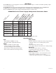
ower Supply Output Specifications:
Stand-by Specifications (total current shown):
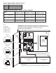
--- DC
+
L G N
PTC3
NC C NO NC C NO
+
BAT ---
DC
24V - OPEN
12V - CLOSED
AC FAIL
RL2
BAT FAIL
RL1
RL3
SW1
Fuse
Door
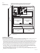
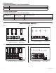
CAUTION: De-energize unit prior to servicing. For continued protection
against risk of electric shock and fire hazard replace fuse with the same type
and rating 3.5A, 250V. Replace fuse cover before energizing.
Do not expose to rain or moisture.
Green
Lead
Battery connection (non power-limited)
Wire
Strap
(from
Enclosure
to Door)
220VAC
power mains
Battery & AC Supervision
Circuit
(power-limited)
F
use Cover
Power
Distribution
Module(s)
INPUT
Divider
24V - OPEN
12V - CLOSED
SW1
power-limited
NC C NO NC C NO
A
C FAIL
B
AT FAIL
Green
Lead
CAUTION: When power supply board is set for 12VDC use only one (1) 12VDC
stand-by battery.
Keep power-limited wiring separate from non-power limited. Use minimum .25" spacing.
12VDC Rechargeable Battery
(optional)
12VDC Rechargeable Battery
(optional)
AC Delay
AC Delay
Fig. 1
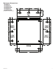
AL400X220
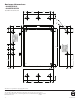
AL400PD4220
AL400PD4CB220
AL400PD8220
AL400PD8CB220
Fig. 1a
Fig. 1b
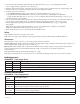
Output Switch Position
12VDC SW1 - CLOSED (Fig. 1b)
24VDC SW1 - OPEN (Fig. 1b)
Output
4 hr. of Stand-by &
5 Minutes of Alarm
24 hr. of Stand-by &
5 Minutes of Alarm
60 hr. of Stand-by &
5 Minutes of Alarm
12VDC / 40AH Battery
Stand-by = 4.0 amp
Alarm = 4.0 amp
Stand-by = 1.0 amp
Alarm = 4.0 amp
Stand-by = 300mA
Alarm = 4.0 amp
24VDC / 12AH Battery --------
Stand-by = 200mA
Alarm = 3.0 amp
--------
24VDC / 40AH Battery
Stand-by = 3.0 amp
Alarm = 3.0 amp
Stand-by = 1.0 amp
Alarm = 3.0 amp
Stand-by = 300mA
Alarm = 3.0 amp
Fig. 1c