AL400X220 Series Power Supply/Charger Installation Guide Models Include: • AL400X220 - Single Output • AL400PD4220 - Four (4) Fused Outputs • AL400PD8220 - Eight (8) Fused Outputs • AL400XPD16220 - Sixteen (16) Fused Outputs • AL400PD4CB220 - Four (4) PTC Outputs • AL400PD8CB220 - Eight (8) PTC Outputs • AL400XPD16CB220 - Sixteen (16) PTC Outputs For a red enclosure, add an “R” suffix to the part # e.g. AL400PD8R220 Rev.
Overview: The AL400X220 is a power supply that converts a 220VAC 50/60Hz input, to a 12VDC or 24VDC regulating output, (see specifications below). The AL400X220 is the base power supply unit for the multi-output power supply/charger series: AL400PD4220, AL400PD4CB220, AL400PD8220, AL400PD8CB220, AL400XPD16220, AL400XPD16CB220 (Refer to AL400X220 Series Power Supply Configuration Reference Chart below).
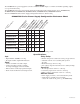
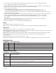
Power Supply Output Specifications: Output 12VDC 24VDC Switch Position SW1 - CLOSED (Fig. 1b) SW1 - OPEN (Fig. 1b) Stand-by Specifications (total current shown): Output 4 hr. of Stand-by & 5 Minutes of Alarm 24 hr. of Stand-by & 5 Minutes of Alarm 60 hr. of Stand-by & 5 Minutes of Alarm 12VDC / 40AH Battery Stand-by = 4.0 amp Alarm = 4.0 amp Stand-by = 300mA Alarm = 4.0 amp 24VDC / 12AH Battery -------- 24VDC / 40AH Battery Stand-by = 3.0 amp Alarm = 3.0 amp Stand-by = 1.0 amp Alarm = 4.
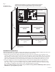
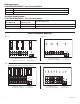
Fig. 2 CAUTION: De-energize unit prior to servicing. For continued protection against risk of electric shock and fire hazard replace fuse with the same type and rating 3.5A, 250V. Replace protective cover before energizing unit. Do not expose to rain or moisture. AL400XPD16220 AL400XPD16CB220 DC PTC3 Switch Position: 24VDC = SW1 OPEN 12VDC = SW1 CLOSED 24V - OPEN SW1 12V - CLOSED 3.
3. Set the unit to the desired DC output voltage by setting SW1 (Fig. 1b, pg. 3) to the appropriate position (Power Supply Voltage Output Selections Chart, pg. 3). 4. Measure output voltage before connecting any devices to ensure proper operation. Improper or high voltage will damage these devices. When servicing the unit, AC mains should be removed. 5. Connect devices to be powered: a. For AL400X220 Power Supply connect devices to terminals marked [- DC +] (Fig. 1, pg. 3). b.
LED Diagnostics: PD4A/PD4ACB/PD8A/PD8ACB - Power Distribution Module Green (AC) Power Distribution Module Status ON Normal operating condition. OFF No Power Output. Terminal Identification: PD4A/PD4ACB/PD8A/PD8ACB - Power Distribution Module Terminal Legend PD4A/PD4ACB 1P to 4P 1N to 4N Terminal Legend PD8A/PD8ACB 1P to 8P 1N to 8N Function/Description Normal operating condition. No Power Output. Power Distribution Module(s): Fig. 3b Fig. 3a Replace fuses with the same type and rating 3.5A, 250V.
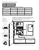
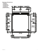
Enclosure Dimensions: • AL400X220 • AL400PD4220 • AL400PD4CB220 • AL400PD8220 • AL400PD8CB220 13.5”H x 13”W x 3.
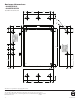
Enclosure Dimensions: • AL400XPD16220 • AL400XPD16CB220 15.5”H x 12”W x 4.5”D 1.500" 4.615" 4.615" 1.500" 1.750" 1.375" 1.125" 4.500" 12.230" 1.250" 4.500" 1.100" 1.250" 1.100" 0.910" 0.910" 1.500" 1.500" 2.000" 15.500" 2.000" 5.000" 5.000" 0.790" 1.250" 1.100" 1.250" 1.750" 1.500" 4.615" 4.615" 1.500" Altronix is not responsible for any typographical errors. Altronix Corp. 140 58th Street, Brooklyn, New York 11220 USA, 718-567-8181, fax: 718-567-9056 web site: www.altronix.