
Installation Guide


- 4 - AL400ULX Series
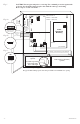
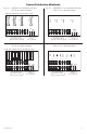
Fig. 1
Power
Distribution
Module(s)
+
DC ---
NC C NO NC C NO
+
BAT ---
AC DC Bat
Risk of Fire,
Replace Fuses
As Marked
AC Fail
Bat Fail
J1
SW1
5A 250V
15A 250V
AC Delay
15
L G N
Door
CAUTION: De-energize unit prior to servicing. For continued protection against risk
of electric shock and fire hazard replace fuse with the same type and rating.
Do not expose to rain or moisture.
Green
Lead
Battery connection (non power limited)
Switch Position:
24VDC = SW1 OFF
12VDC = SW1 ON
Wire
Strap
(from
Enclosure
to Door)
115VAC
power mains
non-power
limited
Battery & AC
Supervision
Circuit
(power limited)
-
Divider
power-limited
For 12VDC Operation
use hook-up in the
inset on the right
CAUTION: When power supply board is set for 12VDC use only one (1) 12VDC stand-by battery.
Keep power limited wiring separate from non-power limited. Use minimum 0.25" spacing.
12VDC Rechargeable Battery
(optional)
12VDC Rechargeable Battery
(optional)
SW1
NC C NO NC C NO AC Fail
Bat Fail
J1
AC Delay
OFF - 24V
ON - 12V
ON
1
OFF - 24V
ON - 12V
ON
1
Battery & AC
Supervision Circuit
(power-limited)
Fig. 1a
Fig. 1b
Fig. 1c