
Installation Instructions Owner manual

Maintenance:
Unitshouldbetestedatleastonceayearfortheproper
operationasfollows:
OutputVoltageTest:Undernormalloadconditions,theDC
outputvoltageshouldbecheckedforpropervoltage
level (Power Supply Output Specifications Chart).
BatteryTest:Undernormalloadconditionscheckthatthe
batteryisfullycharged,checkspecifiedvoltagebothat
batteryterminalandattheboardterminalsmarked[+BAT--]
toinsurethereisnobreakinthebatteryconnectionwires.
Note:Maximumchargingcurrentunderdischargeis400mA.
Note:Expectedbatterylifeis5years,howeveritisrecom-
mendedchangingbatteriesin4yearsorlessifneeded.
LED Diagnostics:
Red (DC) Green (AC) Power Supply Status
ON ON Normalfunction
ON OFF Batterybackupispoweringoutput
OFF ON NoDCoutput
OFF OFF LossofAC.Dischargedormissingstand-bybattery.NoDCoutput.
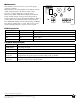
Terminal Identification:
Terminal Legend Function/Description
XFMRINPUT Low voltage AC input.
+DCOUT--- Continuouspositive(+)DCpoweroutputvoltage.Commonnegative(-)output(ground).
+BAT--- Stand-bybatteryconnections.
ACFAIL
NO,C,NC
IndicateslossofACe.gconnectaudibledeviceoralarmpanel.Relayisnormally
energizedwhenACpowerispresent.Contactrating1amp@28VDC.
LOWBAT
NO,C,NC
Indicateslowbatteryconditione.gconnectaudibledeviceoralarmpanel.Relayisnormally
energized.Contactrating1amp@28VDC.
VR1
AC ON
XFMR INPUT
+ BAT - -- -+ DC OUT - -- -
AC F AIL
NO C NC
LOW BA T
NO C NC
DC ON
MEMBER
Altronixisnotresponsibleforanytypographicalerrors.
14058thStreet,Brooklyn,NewYork11220USA,718-567-8181,fax:718-567-9056
website:www.altronix.com,e-mail:info@altronix.com,LifetimeWarranty,MadeinU.S.A.
IIAL201ULB-Rev.041901 J17K
Fig. 1