
Installation Instructions User guide
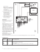

Terminal/Switch Identification:
Terminal Function/Description
Legend
TRG1 & TRG2 These input terminals are designed to connect to the normally closed
outputs of an access control or fire alarm relay. These terminals control [LOCK+],
and [STRIKE+], as well as AL175ULX2 output relay contacts [N.C., N.O., C]
LOCK+ This terminal provides DC output voltage when [TRG1] and [TRG2] are shorted
together and are typically used to power Mag Locks.
STRIKE+ This terminal provides DC output voltage when [TRG1] and [TRG2] are unshorted
and are typically used to power Electric Strikes.
N.C., N.O., C Isolated dry Form “C” contacts. Shorting [TRG1] and [TRG2] together causes
these contacts to switch. They are typically used for controlling multiple
AL175ULX2s with fire alarm tie-in (Fig. 4, pg. 4).
AUX + Continuous positive (+) DC power output voltage.
It is not affected by TRG1, TRG2 operation.
COM - Common negative (-) output (ground).
FACP Spare wiring terminal used for fire alarm tie-in application (Fig. 3, pg. 4).
BAT+, BAT- Stand-by battery connections.
SW2 Momentary reset button (on front door) is used as a manual power supply reset
after fire alarm system is restored.
AUX + AUX neg (-) output (ground).
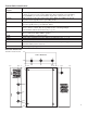
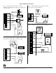
Enclosure Dimensions:
15.5”H x 12”W x 4.5”D
3
.875"
1"
0
00
0
10.75"
1.5"
6"
10.5"
2"
0
1.25"
4.5"
12"
15.5"
4.5"
4.5"
1.25"
1.25"
14.25"
13.5"
10"
6.625"
TOP & BOTTOM