
Installation Instructions User guide

[N.C., N.O., C].
Note: To meet UL requirements,
AC Supervisory outputs must be
connected to the zone of Alarm
Control Panel or
to visual AC trouble indicator.
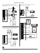
6. For Access Control Device &
Fire Alarm Interface
connections refer to desired
Application Diagrams
(pg. 4) and Terminal
Identification Chart (pg. 3).
7. Secure enclosure door with
the screws supplied, to
assure proper ground.
Maintenance:
Unit should be tested at least once
a year for the proper operation
as follows:
Output Voltage Test: Under normal
load conditions, the DC output
voltage should be checked for proper
voltage level (see Power Supply
Output Specifications Chart).
Battery Test: Under normal load con-
ditions check that the battery is fully
charged, check specified voltage both
at battery terminal and at the board
terminals marked [- BAT +] to insure
there is no break in the battery
connection wires.
Note: Maximum charging current
under discharge is 0.40 amp.
Note: Expected battery life is 5 years, however it is recommended changing batteries in 4 years or less if needed.
LED Diagnostics:
Red (DC) Green (AC) Power Supply Status
(on front door)
ON ON Normal function
ON OFF Battery backup is powering output
OFF ON No DC output
OFF OFF Loss of AC. Discharged or missing stand-by battery. No DC output.
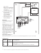
ALTRONIX CORP.
AL175ULB
BKLYN, NY 11220
MADE IN U.S.A.
SW1
VR1
+ BAT -- AC AC
LOCK + STRIKE + COM - AUX + FACP AUX -
NC NO C TRG1 TRG2
SW1 CLOSED -24V
OPEN - 12V
NC
C
NO
AC FAIL
XFMR
Green
Lead
(ground)
Stand-by
Battery
(optional)
Constant output
(not affected
by trigger)
Switched
DC output
(trigger control)
Black
Lead
White
Lead
115VAC input
60 Hz,
.6 amps
AC
DC
JUMPER
Reset
Switch
AC Power
LED
AC
Molex
Connector
2
Altronix is not responsible for any typographical errors. Product specifications are subject to change without notice.