
Installation Manual


AL175ULX - 1 -
Overview:
The AL175ULX is a power-limited power supply/charger that will convert 115VAC / 60Hz input into two individually
PTC protected 12VDC or 24VDC outputs (see specifications). It is intended for use in applications requiring UL Listing
for Access Control System Units (UL 294) and applications requiring an interface with the Fire Alarm Control Panels.
Specifications:
Power Supply Output Specifications:
Output VDC Switch Position Max. Stand-by Load DC Max. Alarm Load DC Battery (optional)
12VDC SW1 OFF 1.75 amp 1.75 amp 12VDC
24VDC SW1 ON 1.75 amp 1.75 amp 24VDC
Stand-by Specifications:
Output 4 hr. of Stand-by & 5 Minutes of Alarm
12VDC / 7 AH Battery
Stand-by = 1.25 amp
Alarm = 1.25 amp
24VDC / 7 AH Battery
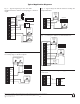
Installation Instructions:
Wiring methods shall be in accordance with the National Electrical Code/NFPA 70/NFPA 72/ANSI, and with all local
codes and authorities having jurisdiction. Product is intended for indoor use only.
See Terminal Identification Chart on Pg. 3 for a description of each terminal function.
1. Mount unit in the desired location. Mark and predrill holes in the wall to line up with the top two keyholes in the
enclosure. Install two upper fasteners and screws in the wall with the screw heads protruding. Place the enclosure’s
upper keyholes over the two upper screws; level and secure. Mark the position of the lower two holes. Remove the
enclosure. Drill the lower holes and install two fasteners. Place the enclosure’s upper keyholes over the two upper
screws. Install the two lower screws and make sure to tighten all screws (Enclosure Dimensions, pg. 3).
Secure enclosure to earth ground.
2. Connect AC power to the black and white flying leads of the transformer. Secure green wire lead to earth ground.
Use 18 AWG or larger for all power connections (Battery, DC output). Use 22 AWG to 18 AWG for power-
limited circuits (trigger inputs, dry outputs).
Keep power-limited wiring separate from non power-limited wiring (115VAC / 60Hz Input, Battery Wires).
Minimum 0.25” spacing must be provided.
CAUTION: Do not touch exposed metal parts. Shut branch circuit power before installing or servicing equipment.
There are no user serviceable parts inside. Refer installation and servicing to qualified service personnel.
3. Set the AL175ULX to the desired DC output voltage by setting switch SW1 to the appropriate position (refer to
Power Supply Output Specification Table).
Agency Listings:
• ULListedforAccessControlSystems(UL294).
CUL Listed - CSA Standard C22.2
No.205-M1983, Signal Equipment.
• MEA-NYCDept.ofBuildingsApproved.
• CSFM-CaliforniaStateFireMarshalApproved.
• ConformstoNFPA101lifesafetycodes
.
Input:
• Input115VAC/60Hz,0.6amp.
Output:
• Selectable12VDCor24VDCpower-limitedoutputs.
• Class2Ratedpower-limitedoutputs.
• 1.75ampcontinuoussupplycurrent@12VDCor24VDC.
• Filteredandelectronicallyregulatedoutput.
• Shortcircuitandthermaloverloadprotection.
Battery Backup:
• Maximumchargecurrent:400mA.
• Automaticswitchovertostand-bybatterywhenACfails.
Supervision:
• ACfailsupervision(form“C”contacts).
• Drytriggeroutput(form“C”contacts).
Fire Alarm Interface:
• Drytriggerinput.
Visual Indicators:
• ACinputandDCoutputLEDindicators.
Added Features:
• Includespowersupply,transformerandenclosure.
Enclosure Dimensions:
13.5”x13”x3.25”(342.9mmx330.2mmx82.55mm).
AL175ULX
Access Control Power Supply/Charger
Altronix Corp.
140 58th St. Brooklyn, NY