
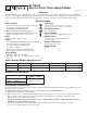
Installation Instructions Instruction Manual
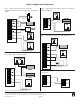

Terminal Identification:
T
erminal Function/Description
Legend
TRG1 & TRG2 These input terminals are designed to connect to the normally closed
outputs of an access control or fire alarm relay. These terminals control [LOCK+],
and [STRIKE+], as well as AL175ULX output relay contacts [N.C., N.O., C]
LOCK+ This terminal provides DC output voltage when [TRG1] and [TRG2] are shorted
together and are typically used to power Mag Locks.
STRIKE+ This terminal provides DC output voltage when [TRG1] and [TRG2] are unshorted
and are typically used to power Electric Strikes.
N.C., N.O., C Isolated dry Form “C” contacts. Shorting [TRG1] and [TRG2] together causes these contacts to
switch. They are typically used for controlling multiple AL175ULXs with fire alarm tie-in
(Fig. 5 and Fig. 6, pg. 4).
AUX + Continuous positive (+) DC power output voltage. It is not affected by TRG1, TRG2 operation.
COM - Common negative (-) output (ground).
F
ACP Spare wiring terminal used for fire alarm tie-in application
(Fig. 4, pg. 4).
+ BAT -- Stand-by battery connections.
AC FAIL Used to notify loss of AC e.g connect audible device or alarm panel relay normally energized
N.C., C, N.O. When AC power is present. Contact rating 1 amp @ 28VDC.
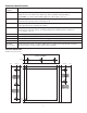
Enclosure Dimensions:
13”H x 13.5”W x 3.25”D
00
0
.81"
0
1.1875"
1.1875"
3.25"
3.25"
0 1.1875" 3.25".75" 1.5" 6.25" 11"
1.4"
6.5"
5.5"
1.4"
11.66"
12.1"
13"
12.5"
11.75"
TOP ONLY
- 3 -