
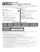
Installation Manual

LED Diagnostics:
Red (DC) Green (AC) Power Supply Status
ON ON Normal operating condition.
ON OFF Battery backup is powering output.
OFF ON No DC output.
OFF OFF Loss of AC. Discharged or missing stand-by battery. No DC output.
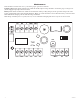
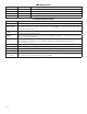
Terminal Identification:
Terminal Legend Function/Description
AC Low voltage AC input.
TRG1&TRG2
These input terminals are designed to connect to the normally closed outputs of an access control or
realarmrelay.Theseterminalscontrol[LOCK+],and[STRIKE+],aswellasAL175ULBoutput
relay contacts [N.C., N.O., C]
LOCK +
ThisterminalprovidesDCoutputvoltagewhen[TRG1]and[TRG2]areshortedtogetherandare
typically used to power Mag Locks.
STRIKE+
ThisterminalprovidesDCoutputvoltagewhen[TRG1]and[TRG2]areunshortedandaretypically
used to power Electric Strikes.
N.C., N.O., C
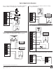
IsolateddryForm“C”contacts.Shorting[TRG1]and[TRG2]togethercausesthesecontactsto
switch. They are typically used for controlling multiple AL175ULBs with fire alarm tie-in
(Fig. 4 and Fig. 5, pg. 4).
AUX+ Continuouspositive(+)DCpoweroutputvoltage.ItisnotaffectedbyTRG1,TRG2operation.
COM -- Common negative (-) output (ground).
FACP Spare wiring terminal used for fire alarm tie-in application (Fig. 3, pg. 4).
+ BAT -- Stand-by battery connections.
AC Fail
N.C., C, N.O.
Used to notify loss of AC e.g connect audible device or alarm panel relay normally energized when
ACpowerispresent.Contactrating1amp@28VDC.
AL175ULB - 3 -