
Installation Manual
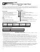

- 2 - AL175UL
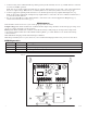
115VAC input
60 Hz,
0.6 amp
Green Lead
(ground)
Black
Lead
White
Lead
Stand-by
Battery
(optional)
Constant output
(Not affected
by trigger)
XFMR
Switched
DC output
(trigger control)
NC
DC
AC
C TRG1 TRG2
ACAC+ BAT --
COM -- AUX --LOCK + AUX +FACPSTRIKE +
SW1 ON - 24V
OFF - 12V
SW1
VR1
NO
NC CNO
AC FAIL
ON
Fig. 1
5. Connectbatterytotheterminalsmarked[+BAT-](batteryleadsincluded).Usetwo(2)12VDCbatteriesconnected
in series for 24VDC operation.
Note:ForAccessControlapplicationsbatteriesareoptional.Whenbatteriesarenotused,alossofACwillresultin
thelossofoutputvoltage.Whentheuseofstand-bybatteriesaredesired,theymustbeleadacidorgeltype.
6. ConnectappropriatesignalingnotificationdevicestoACFailsupervisoryrelayoutputsmarked[NC,NO,C].
Note:TomeetULrequirements,ACSupervisoryoutputsmustbeconnectedtothezoneofAlarmControlPanelor
to visual AC trouble indicator.
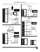
7. For Access Control Device & Fire Alarm Interface connections refer to desired Application Diagrams (pg. 4)
and (Terminal Identification Chart, pg. 3).
Maintenance:
Unitshouldbetestedatleastonceayearfortheproperoperationasfollows:
Output Voltage Test:UndernormalloadconditionstheDCoutputvoltageshouldbecheckedforpropervoltagelevel
(see Power Supply Output Specifications Chart).
Battery Test:Undernormalloadconditionscheckthatthebatteryisfullycharged,checkspecifiedvoltageboth
atthebatteryterminalandattheboardterminalsmarked[-BAT+]toensurethatthereisnobreakinthebattery
connection wires.
Note:Maximumchargingcurrentunderdischargesis400mA.
Note:Expectedbatterylifeis5years;however,itisrecommendedchangingbatteriesin4yearsorlessifneeded.
LED Diagnostics:
Red (DC) Green (AC) Power Supply Status
ON ON Normal function.
ON OFF Batterybackupispoweringoutput.
OFF ON No DC output.
OFF OFF Loss of AC. Discharged or missing stand-by battery. No DC output.