
Spec Sheet


VR1
NO NOGND GND FA CP1 FAC P2 STRIKE+
COM-- LOCK+
+ AUX --
TRIG
INPUT
RESET
SW1
+ BAT --
XFMR
SW2:
12VDC - Open
24VDC - Closed
XFMR
115VAC
50/60 Hz,
.6 amp
Blue Lead
Ye llow Lead
White
Lead
Black
Lead
Green
Lead
(ground)
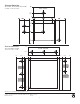
STEP 1:
Use these holes to mount
AL125ULB b
y pushing the nylon
circuit board f
asteners
(Fig
. 1A)
through the back of the enclosure.
Nylon fasteners will snap into place.
(Fig. 1A)
Nylon Fastener
STEP 2:
Mount AL125ULB circuit board to nylon
f
asteners by pressing down circuit board onto
nylon fasteners.
Note: Springlock on fasteners is used to remove
AL125ULB circuit board.
Note: Four (4) nylon fasteners are
provided in the AL125ULB carton.
Springlock
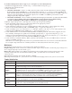
Fig. 1 - Board Installation Diagram:
Note:
- AL125UL, AL125ULX - Connect blue and yellow
leads of transformer to terminals marked [XFMR]
on the power supply board.
- AL125ULP, AL125ULE - Connect 24VAC @ 40VA
from UL Listed plug-in transformer to the terminals
marked [XFMR]on the power supply board.
VR1
NO NOGND GND
FACP1 FAC P2
STRIKE+
COM-- LOCK+
+ AUX --
TRIG
INPUT
RESET
SW1
+ BAT --
XFMR
SW2:
12VDC - Open
24VDC - Closed
Normal Open
Access Control
Triggering
Device
Normal Open
Reset Device
2.2K EOL
(supplied)
MAG LOCK
NC
FACP
NO
FACP
{ }
Card
Reader
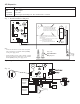
Fig. 2 - Application Diagram:
LED Diagnostics:
Red Power Supply Status
ON Normal function.
OFF No DC output.
Slow Blink Loss of AC.
Rapid Blink Unit is triggered, awaiting reset. Fire alarm interface activated.
Fig. 2A
VR1
NO NOGND GND
FACP1 FACP2
STRIKE+
COM-- LOCK+
+ AUX --
TRIG
INPUT
RESET
SW1
+ BAT --
XFMR
SW2:
12VDC - Open
24VDC - Closed
Normal Open
Access Control
Triggering
Device
Normal Open
Reset Device
2.2K EOL
(supplied)
MAG LOCK
NC
FACP
NO
FACP
{ }
Card
Reader
ELECTRIC
STRIKE
STRIKE+
LOCK+
Com-
- 3 -