
Installation Instructions Manual

AL1042ULADA - 5 -
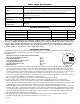
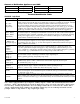
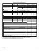
Amount of Notification Appliances per NAC:
Amseco 27perNAC* SystemSensor® 32perNAC*
Faraday 39perNAC* CooperWheelock® 32perNAC*
Gentex® 32perNAC*
*Not to exceed a maximum of 2.5 amp per NAC.
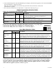
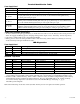
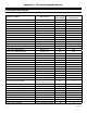
Terminal Identification Table:
AL842LGK - Logic Board
Terminal Legend Function/Description
IN1+,IN1-
IN2+,IN2-
(Supervised)
Theseterminalsconnecttothe12VDCor24VDCFACPnotificationappliancecircuitoutputs.
(ClassA,StyleZorClassB,StyleW,Y)Inputtriggervoltageis8-33VDC@5mAmin.Terminal
polarityisshowninalarmcondition.Duringanalarmconditiontheseinputswillcause
theselectedoutputschosentodrivenotificationappliances.Thedesignatedoutputsaresetby
outputswitches[OUT1throughOUT4](Output Programming Selection Table, pg. 4).Atrouble
conditiononanoutputloopwillcausethecorrespondinginputtotriptheFACPbyopeningthe
FACPloop.Analarmconditionwillalwaysoverridetroubletodrivenotificationappliances.
RET1+,RET1-
RET2+,RET2-
(Supervised)
ForClassA,StyleZhookupstheseterminalpairsreturntoFACPNAC1and/orNAC2.
ForClassB,StyleW,YhookupstheFACPEOLresistorfromtheNAC1and/orNAC2outputs
areterminatedattheseterminals.Optionally,othernotificationappliancesoradditionalsignaling
circuitpowersuppliesmaybeconnectedtotheseterminals.IfthisoptionischosentheEOL
resistormustbeterminatedatthelastdevice.
C“DRY1”NC
C“DRY2”NC
(Dryinputtrigger)
Anopenacrosstheseinputs,willcausetheselectedoutputschosentodrivenotificationappli-
ances.Thedesignatedoutputsaresetbyoutputswitches[OUT1throughOUT4](Output
Programming Selection Table, pg. 4).Notetheseinputsareunidirectionalandwillnotreporta
troubleconditiontotheFACP.
+OUT1--
+OUT2--
+OUT3--
+OUT4--
(Supervised)
Notificationappliancesareconnectedtotheseregulatedoutputs(see Application Guide, pgs.
2-4).Eachpower-limitedoutputwillsupply2.5amp.Totalsupplycurrentis10amp(see note
below).Outputsarecontrolledbydesignatedinput1[IN1]orinput2[IN2] (Output Programming
Selection Table, pg. 4).Maximumlinelossorvoltagedrop(testedwith2.5V).
+Loop1--
+Loop2--
+Loop3--
+Loop4--
UsedforClassA,StyleZhook-upstoterminateloopsoriginatingon
[OUT1],[OUT2],[OUT3],and[OUT4]respectively.
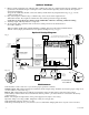
C“FAULT”NC
(Common
troubleinput)
Anopencircuitacrossthispairofterminalswillcause[INP1andINP2]LEDsto
simultaneouslysignalatroubleconditionbacktotheFACP(Typicallyusedtoreport
ACorBATFail).(Fig. 3a, pg. 8).
NC,C,NO
(Common
troubleinput)
Thesearedrycontacttroubleoutputsthatreportanygeneralloop/systemtroubleconditions.
(Typicallyusedtotriggeradigitalcommunicatororotherreportingdevices).
(form“C”contact1amp/28VDC0.35PowerFactor)(Fig. 3, pg. 8).
--AUX+
Thisseparate1ampmax.auxiliaryspecialapplicationpoweroutputcircuitistypicallyusedto
powerelectromagneticdoorholdersthatkeepfireandsmokedoorsopenundernormalconditions.
See Appendix A, pgs. 10-11.
--AUX2+
Thisseparateauxiliaryregulatedpoweroutputcircuitsuppliesupto1ampduringstand-byand
alarmcondition.SincethisoutputisnotdisconnectedfromitsloadduringACpowerfailureusethe
(Battery Calculation Worksheet, pg. 9)todeterminebatterysizeand/orallowablestand-byandalarm
current.
+DC-- 24VDCfrompowersupply.
Note: Unit is equipped with two (2) 1 amp max. auxiliary outputs: “AUX1” will automatically disconnect when
AC is lost. “AUX2” will remain battery backed up during power outage. For loads connected to “AUX2” please,
refer to battery “Stand-by Specifications” above for ratings. When loads are connected to the “AUX1” and or
“AUX2” outputs during alarm condition, the remaining outputs may, not exceed 10 amp total alarm current.
(example: AUX1 = 1 amp, AUX2 = 1 amp, outputs up to 8 amp).