
Installation Instructions

AL1024ULXseries - 5 -
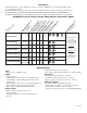
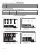
LED Diagnostics:
PD4UL/PD4ULCB/PD8UL/PD8ULCB - Power Distribution Module
G
reen Power Distribution Module Status
ON Normal operating condition.
OFF No Power Output.
Terminal Identification:
PD4UL/PD4ULCB/PD8UL/PD8ULCB - Power Distribution Module
Terminal Legend Function/
PD4UL/PD4ULCB PD8UL/PD8ULCB Description
1P to 4P 1P to 8P Positive DC power outputs.
1N to 4N 1N to 8N Negative DC power outputs.
L
ED
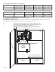
F1 F2 F3 F4
1P
1N
2P
2N
3P
3N
4P
4N
Non-Power Limited
DC Output to devices
1P-4P Power Outputs,
1N-4N Common Outputs
()
From Power Supply
Board
(Factory Installed)
Replace fuses with the same type and rating 3.5A, 250V.
Fig. 2A
Fig. 3A
Power Distribution Module(s):
INPUT
LED
F1 F2 F3 F4
POWER OUTPUTS
1P
1N
2P
2N
3P
3N
4P
4N
Class 2 Rated Power Limited
DC Output to devices
1P-4P Power Outputs,
1N-4N Common Outputs
From Power Supply
Board
(Factory Installed)
()
Fig. 2B
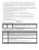
N
COMMON POWER OUTPUTS
P
FUSED POWER OUTPUTS
1 2 3 4 5 6 7 8
D1
INPUT
R1
LED
From Power Supply
Board
(Factory Installed)
Replace fuses with the same type and rating 3.5A, 250V.
Non- Power Limited
DC Output to devices
1P-8P Power Outputs,
1N-8N Common Outputs
()
N
COMMON POWER OUTPUTS
P
FUSED POWER OUTPUTS
1 2 3 4 5 6 7 8
D1
INPUT
R1
LED
From Power Supply
Board
(Factory Installed)
Class 2 Rated Power Limited
DC Output to devices
1P-8P Power Outputs,
1N-8N Common Outputs
()
Fig. 3B