
Installation Instructions

AL1024ULXseries - 3 -
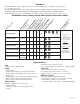
Stand-by Specifications (total current shown):
O
utput 15 Min. of Stand-by & 4 hr. of Stand-by & 24 hr. of Stand-by & 60 hr. of Stand-by &
5 Mins. of Alarm 5 Mins. of Alarm 5 Mins. of Alarm 5 Mins. of Alarm
24VDC / 12AH Battery Stand-by = 8 amp Stand-by = 1.5 amp Stand-by = 200mA Stand-by = 100mA
Alarm = 10 amp Alarm = 10 amp Alarm = 10 amp Alarm = 10 amp
Output 15 Min. of Stand-by & 4 hr. of Stand-by & 24 hr. of Stand-by & 60 hr. of Stand-by &
15 Mins. of Alarm 5 Mins. of Alarm 15 Mins. of Alarm 15 Mins. of Alarm
24VDC / 65AH Battery Stand-by = 8.0 amp Stand-by = 1.5 amp Stand-by = 500mA
Alarm = 10 amp Alarm = 10 amp Alarm = 10 amp
See battery size calculation worksheet for other batteries (
Page 7).
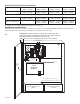
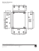
Installation Instructions:
Wiring methods shall be in accordance with the National Electrical Code/NFPA 70/NFPA 72/ANSI, and with all local
codes and authorities having jurisdiction. Product is intended for indoor use only.
-- DC +
B
AT FAIL
NO C NC NO C NC
+
BAT ---
DC
AC FAIL
L
G N
A
C
10A
250V
15A
250V
Green
L
ead
Battery connection (non power limited)
Door
Wire Strap
(from
Enclosure
to Door)
115VAC
power mains
non-power limited
Divider
CAUTION: De-energize unit prior to servicing. For continued protection
against risk of electric shock and fire hazard replace fuses with the same type
and rating: Input fuse 10A, 250V, Battery fuse 15A, 32V.
Replace fuse cover before energizing. Do not expose to rain or moisture.
INPUT
1
2
Power
Distribution
Module(s)
Battery and AC Supervision Circuit
(power limited).
Fuse
Cover
non-power limited
Class 1
Green Lead
Keep power limited wiring separate from non-power limited. Use minimum .25" spacing.
12VDC Rechargeable Battery
(optional)
12VDC Rechargeable Battery
(optional)
Fig. 1