
Installation Instructions

Agency Listings:
• ULRecognizedcomponentforAccessControl
SystemUnits(UL294),PowerSuppliesfor
FireProtectiveSignalingSystems(UL1481).
Input:
• Input115VAC/60Hz,4.2amp.
Output:
• 24VDCoutput(UL1481).
• 8ampcontinuoussupplycurrentwith10amp
supplycurrentduringalarm.
• 24VDC@10amp.(UL294).
• Filteredandelectronicallyregulatedoutput.
• MaximumRipple:250mVP/P
Battery Backup:
• Built-inchargerforsealedleadacidorgeltypebatteries.
Battery Backup (cont’d):
• Maximumchargecurrent3.6amp.
• Automaticswitchovertostand-bybattery
whenACfails.
• Zerovoltagedropwhenswitchedovertobatterybackup.
Visual Indicators:
• ACinputandDCoutputLEDindicators.
Supervision:
• ACfailsupervision(form“C”contacts).
• Lowbatteryandbatterypresencesupervision
(form“C”contacts).
Additional Features:
• Shortcircuitandthermaloverloadprotection.
Board Dimensions (W x L x H approximate):
4.5”x8.4”x1.9”(114.3mmx213.36mmx48.26mm)
Stand-by Specifications:
Output
15 min. of Stand-by &
5 min. of Alarm
4 hr. of Stand-by &
5 min. of Alarm
24 hr. of Stand-by &
5 min. of Alarm
60 hr. of Stand-by &
5 min. of Alarm
24VDC/12AH
Battery
Stand-By=8amp
Alarm=10amp
Stand-By=1.5amp
Alarm=10amp
Stand-By=200mA
Alarm=10amp
Stand-By=100mA
Alarm=10amp
Output
15 min. of Stand-by &
5 min. of Alarm
4 hr. of Stand-by &
5 min. of Alarm
24 hr. of Stand-by &
15 min. of Alarm
60 hr. of Stand-by &
15 min. of Alarm
24VDC/65AH
Battery
-----------------------------------------------
Stand-By=8.0amp
Alarm=10amp
Stand-By=1.5amp
Alarm=10amp
Stand-By=500mA
Alarm=10amp
Installation Instructions:
TheAL1024ULXB2shouldbeinstalledinaccordancewitharticle760ofTheNationalElectricalCodeaswellas
NFPA72andallapplicableLocalCodes.
1. MounttheAL1024ULXB2inthedesiredlocation/enclosure.
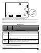
2. ConnectunswitchedACpower(115VAC60Hz)totheterminalsmarked[L,N](Fig. 1, pg. 2).Use14AWGorlarger
forallpowerconnections(Battery,ACinput,DCoutput).Use22AWGto18AWGforpower-limitedcircuits
(ACFail/LowBatteryreporting).
Keep power-limited wiring separate from non power-limited wiring
(115VAC / 60Hz Input, Battery Wires, DC output). Minimum 0.25” spacing must be provided.
CAUTION: Do not touch exposed metal parts. Shut branch circuit power before installing or servicing equipment.
There are no user serviceable parts inside. Refer installation and servicing to qualified service personnel.
3. Measureoutputvoltagebeforeconnectingdevices.Thishelpsavoidingpotentialdamage.
4. Connectdevicestobepoweredtotheterminalsmarked[+DC--](Fig. 1, pg. 2).
5. ForAccessControlapplicationsbatteriesareoptional.Whenbatteriesarenotused,alossofACwillresultinthe
lossofoutputvoltage.Whentheuseofstand-bybatteriesisdesired,theymustbeleadacidorgeltype.Connect
batterytoterminalsmarked[--BAT+](Fig. 1, pg. 2).
6. ItisrequiredtoconnectappropriatesignalingnotificationdevicestoACFAIL&BATFAIL(Fig. 1, pg. 2)
supervisoryrelayoutputs.Use22AWGto18AWGwires.ACFAILwillreportin5minutes.
Todelayreportfor6hourscut“ACDelay”jumper(Fig. 1a, pg. 2).
AL1024ULXB2 - UL Recognized
Power Supply/Charger Rev.082312
Overview:
TheAL1024ULXB2isapowersupplythatconvertsa115VAC/60Hzinputtoa24VDCnonpower-limitedoutput
(seespecifications).
Specifications: