
Installation Manual

ACMseries - 7 -
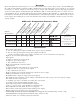
Terminal Identification Tables:
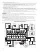
Power Supply Board
T
erminal Function/Description
L
egend
L, G, N Connect 115VAC 60Hz to these terminals: L to hot, N to neutral, G to ground.
- DC + AL400ULACM - 12VDC @ 4 amp or 24VDC @ 3 amp to ACM8 board (power limited).
AL600ULACM - 12VDC/24VDC @ 6 amp to ACM8 board (non-power limited).
AL1012ULACM - 12VDC @ 10 amp to ACM8 board (non-power limited).
AL1024ULACM - 24VDC @ 10 amp to ACM8 board (non-power limited).
AC FAIL Indicates loss of AC power, e.g. connect to audible device or alarm panel. Relay
NC, C, NO normally energized when AC power is present. Contact rating 1 amp @ 28VDC.
AC or brownout fail is reported within 1 minute of event. To delay reporting of up to
6 hrs., cut “AC delay” jumper and reset power to unit.
BAT FAIL Indicates low battery condition, e.g. connect to alarm panel. Relay normally
NC, C, NO energized when DC power is present. Contact rating 1 amp @ 28VDC.
A removed battery is reported within 5 minutes. Battery reconnection is reported
within 1 minute.
Low battery threshold:
12VDC output threshold set @ approximately 10.5VDC (N/A for AL1024ULACM),
24VDC output threshold set @ approximately 21VDC (N/A for AL1012ULACM).
+ BAT - Stand-by battery connections. AL400ULXB, AL600ULXB and AL1012ULXB (Power Supply
Board) maximum char
ge current is .7 amp. AL1024ULXB (Power Supply Board)
maximum charge current is 3.6 amp.
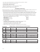
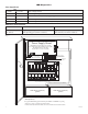
ACM8 Access Power Controller
Terminal
Function/Description
Legend
- Power + 12VDC or 24VDC input from power supply board.
- Control + These terminals can be connected to a separate power limited, UL listed power supply to
provide isolated operating po
wer for the
ACM8 (jumpers J1and J2 Must be removed).
TRIGGER From normally open and/or open collector sink trigger inputs
INPUT 1- INPUT 8 (request to exit buttons, exit pir’s, etc.).
IN, GND
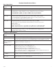
OUTPUT 1-OUTPUT 8 12 to 24 volts AC/DC trigger controlled outputs:
NC, C, NO, COM Fail-Safe [NC positive (+) & COM Negative (-)],
F
ail-Secure [NO positi
ve (+) & COM Negative (-)],
Auxiliar
y output [C positi
v
e (+) & COM Ne
g
ative (-)]
(When using AC power supplies polarity need not be observed),
NC, C, NO become form “C” 5 amp 24VAC/VDC rated dry outputs when fuses are
remo
ved. Contacts shown in a non-triggered state.
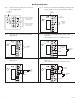
FACP INTERFACE Fire Alarm Interface trigger input from FACP. Trigger inputs can be normally open,
T, + INPUT -- normally closed from an FACP output circuit
(Fig. 4 through 8, pg. 8).
F
A
CP
INTERF
A
CE
F
or
m “C” relay contact rated @ 1 amp 28VDC for alarm reporting.
NC, C, NO (This output has not been evaluated by UL).