
Installation Manual

ACMseries - 5 -
NC C NO COM
OUTPUT 1
LED1
F1
NC C NO COM
OUTPUT 2
I
N GND
1
I
N GND
2
I
N GND
3
I
N GND
4
I
N GND
5
I
N GND
6
I
N GND
7
MAIN
I
N GND
8
LED2 LED3 LED4 LED5 LED6
LED7 LED8
J2
J1
T
RG
NC C NO COM
OUTPUT 3
NC C NO COM
OUTPUT 4
NC C NO COM
OUTPUT 5
NC C NO COM
OUTPUT 6
NO C NC + INP --- T + RET -
NC C NO COM
OUTPUT 7
NC C NO COM
OUTPUT 8
--- +
Power
--- +
Control
F
2
F
3
F6 F7 F8
F
4
F5
J3
3
.5A 250V 3.5A 250V 3.5A 250V3.5A 250V 3.5A 250V3.5A 250V3.5A 250V 3.5A 250V
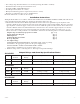
FACP INTERFACE
10A 250V
NC
NO
C
KEYPAD
NORMALLY OPEN
N.O. DOOR
RELEASING DEVICE
ACCESS CONTROL
PANEL
OUTPUT
RELAY
MAG.
LOCK
MAG.
LOCK
ELECTRIC
STRIKE
ELECTROMAGNETIC
DOOR HOLDERS
AC or DC
POWER
SUPPLY
(optional)
AC or DC
POWER
SUPPLY
(req'd.)
FACP
(Fire Alarm
Control Panel)
UL Listed
POWER SUPPLY
For this application
corresponding
fuse F8 must be
removed.
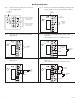
SW1
SW2
SW3
SW4
SW5
SW6
SW7
SW8
FACP Interface Enabled
FACP Interface Disabled
SW1-SW8
FACP Dry
Form "C"
Output
NO C NC
FACP
J2
J1
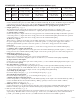
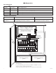
10. Battery and AC Supervision output (Fig. 2, pg. 6):
I
t is required to connect supervisory trouble reporting devices to outputs marked [AC Fail, BAT FAIL] supervisory
r
elay outputs marked [NC, C, NO] to appropriate notification devices. Use 22 AWG to 18 AWG for AC Fail &
L
ow/No Battery reporting. Cut “AC delay” jumper to delay report 6 hour.
Note:A tamper switch must be installed and connected to the appropriate notification device to report a
trouble condition when the enclosure door is open.
11.
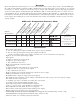
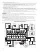
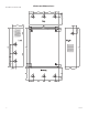
Multiple power supply inputs (Fig. 1, pg. 5):
When using two (2) power supplies jumpers J1 and J2 (located to the left of the power/control terminals) must
be cut
(Fig. 1B, pg. 5 & Fig. 3 pg. 8). Connect power for the ACM8 to the terminals marked [- Control +] and
connect power for the locking devices to the terminals marked [- Power +]. When using DC power supplies polarity
must be observed. When using AC power supplies polarity need not be observed.
Note: For UL compliance the additional power supply must be power limited, UL Listed for Access Control
Systems and accessories.
Maintenance:
Unit should be tested at least once a year for the proper operation as follows:
Output Voltage Test: Under normal load conditions, the DC output voltage should be checked for proper voltage level
(Output Voltage and Stand-by Specification Charts, pg. 3).
Battery Test: Under normal load conditions check that the battery is fully charged, check specified voltage at
the battery terminals and at the board terminals marked [- BAT +] to insure that there is no break in the battery
connection wires.
Note: AL400ULXB, AL600ULXB, AL1012ULXB (Power Supply Board) maximum charge current is .7 amp.
AL1024ULXB (Power Supply Board) maximum charge current is 3.6 amp.
Expected battery life is 5 years, however it is recommended to change batteries within 4 years or less if necessary.
Typical Application Diagram:
Fig. 1
Fig. 1A
Fig. 1B