
Installation Manual

- 4 - ACMseries
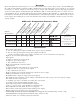
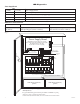
AL1024ULACM - (refer to AL1024ULACM Battery Size Calculation Worksheet, pg. 9)
Voltage Stand-by 15 mins. Stand-by / 4 hr. Stand-by / 24 hr. Stand-by / 60 hr. Stand-by /
B
attery 5 mins. Alarm 5 mins. Alarm 5 mins. Alarm 5 mins. Alarm
2 4 V D C 1 2 A H 7 . 7 a m p / 9 . 7 a m p 1 . 2 a m p / 9 . 7 a m p ------------------------- -------------------------
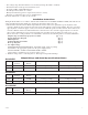
Voltage Stand-by 15 mins. Stand-by / 4 hr. Stand-by / 24 hr. Stand-by / 60 hr. Stand-by /
Battery 5 mins. Alarm 5 mins. Alarm 5 mins. Alarm & 5 mins. Alarm
24VDC 65 AH ------------------------- 7.7 amp / 9.7 amp 1.2 amp / 9.7 amp 200mA / 9.7 amp
4.
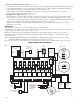
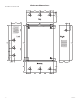
Connect AC (Fig. 2, pg. 6):
Connect unswitched AC power (115VAC 60Hz) to terminals marked [L, G, N]. Use 14 AWG or larger for all power
connections. Secure green wire lead to earth ground.
Keep power limited wiring separate from non-power
limited wiring (115VAC 60Hz Input, Battery Wires). Minimum .25” spacing must be provided.
5. Output options (Fig. 1, pg. 5):
The unit will provide either eight (8) switched power outputs, eight (8) dry form “C” outputs, or any
combination of both switched power and form “C” outputs, plus eight (8) unswitched auxiliary power outputs.
(a) Switched P
ower outputs:
Connect the negative (-) input of the device being powered to the terminal marked [COM]. For Fail-Safe operation
connect the positive (+) input of the device being powered to the terminal marked [NC]. For Fail-Secure operation
connect the positive (+) input of the device being powered to the terminal marked [NO].
(b) Form “C” outputs:
When form “C” outputs are desired the corresponding output fuse (1-8) must be removed. Connect negative (-) of
the power suppl
y directly to the locking device. Connect the positive (+) of the power supply to the terminal
marked [C]. For Fail-Safe operation connect the positive (+) of the device being powered to the terminal
marked NC].
For Fail-Secure operation connect the positive (+) of the device being powered to the terminal marked [NO].
(c) Auxiliary Power outputs (unswitched):
Connect positi
ve (+) input of the device being powered to the terminal marked [C] and the negative (-) of the device
being po
wered to the terminal marked [COM]. Output can be used to provide power for card readers, keypads etc.
6.
Input trigger options (Fig. 1, pg. 5):
(a) Normally Open [NO] input trigger:
Inputs 1-8 are activated by normally open or open collector sink inputs.
Connect de
vices (card readers, k
eypads, request to exit b
uttons etc.) to ter
minals marked [IN] and [GND].
(b) Open Collector Sink inputs:
Connect the access control panel open collector sink positive (+) to the terminal marked [IN] and the negative (-) to
the ter
minal marked [GND].
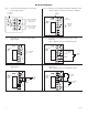
7.
Fir
e
Alarm Interface options
(F
igs. 4 thr
ough 8, pg. 8)
:
A normally closed [NC], normally open [NO] input or polarity reversal input from FACP signaling circuit will
trigger selected outputs. To enable FACP Disconnect for an output open the corresponding switch [SW1-SW8].
To disable FACP disconnect for an output close the corresponding switch [SW1-SW8].
(a)Normally Open [NO] input:
For non-latching hook-up (Fig. 5, pg. 8). For latching hook-up (Fig. 6, pg. 8).
(b)
Normall
y Closed [NC] input:
For non-latching hook-up (Fig. 7, pg. 8). For latching hook-up (Fig. 8, pg. 8).
(c)FACP Signaling Circuit input trigger:
Connect the positi
v
e (+) and ne
g
ati
v
e (-) from the F
ACP signaling circuit output to the terminals marked [+ INP -].
Connect the F
ACP EOL to the terminals marked [+ RET -] (polarity is referenced in an alarm condition).
Jumper J3 must be cut
(Fig. 4, pg. 8).
8.
FACP Dry form “C” output (Fig. 1A, pg. 5):
Connect desired device to be triggered by the unit’s dry contact output to the terminals marked [NO] and [C]
FACP for normally open output or the terminals marked [NC] and [C] FACP for normally closed output.
9.
Batter
y Connections
(F
ig
. 2, pg
. 6)
:
For Access Control applications batteries are optional. If batteries are not used a loss of AC will result in the loss of
output voltage. Batteries must be lead acid or gel type. Connect one (1) 12VDC battery to the terminals marked
[+ BAT -] for 12VDC operation. Use two (2) 12VDC batteries wired in series for 24VDC operation.