
Installation Manual

- 2 - ACMseries
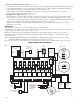
Overview:
T
hese units distribute and switch power to access control systems and accessories. They convert a 115VAC 60Hz input
i
nto eight (8) independently controlled 12VDC or 24VDC fuse protected outputs. These power outputs can be converted
t
o dry form “C” contacts. Outputs are activated by an open collector sink or normally open (NO) dry trigger input from
an Access Control System, Card Reader, Keypad, Push Button, PIR, etc. Units will route power to a variety of access
control hardware devices including: Mag Locks, Electric Strikes, Magnetic Door Holders, etc. Outputs will operate in
both Fail-Safe and/or Fail-Secure modes. The FACP Interface enables Emergency Egress, Alarm Monitoring, or may be
used to trigger other auxiliary devices. The fire alarm disconnect feature is individually selectable for any or all of the
eight (8) outputs.
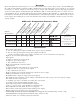
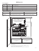
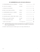
ACM Series Configuration Reference Chart:
AL400ULACM 4 3 8 Yes 1.9 amp 3.5A / 250V
AL600ULACM 6 6 8 No 1.9 amp 3.5A / 250V
AL1012ULACM 10 --- 8 No 1.9 amp 3.5A / 250V
AL1024ULACM --- 10 8 No 4.4 amp 10A / 250V
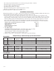
Specifications:
• Power supply input options:
a)
One (1) common power input for ACM8 and lock power (factory installed).
b) Two (2) isolated power inputs (external power supply is required).
(current is determined by the power supply connected, not to exceed a maximum of 10 amp total).
• Eight (8)
Access Control System trigger inputs.
Input options:
a) Eight (8) normally open (NO) inputs.
b) Eight (8) open collector inputs.
c) Any combination of the above.
•
Eight (8) independentl
y controlled outputs.
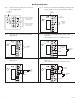
Output options:
a) Eight (8) Fail-Safe and/or Fail-Secure power outputs.
b)
Eight (8) for
m “C” 5 amp rated relay outputs.
c) Any combination of the above.
• Eight (8) auxiliary power outputs (unswitched) (outputs are rated 3.5 amp).
• ACM8 board main fuse is rated at 10 amp.
• Red LEDs indicate outputs are triggered (relays energized).
•
F
ire
Alarm disconnect (latching or non-latching) is individually selectable for any or all of the eight (8) outputs.
F
ire
Alar
m disconnect input options:
a) Normally open (NO) or normally closed (NC) dry contact input.
b) Polarity reversal input from FACP signaling circuit.
•
Alarm output relay indicates that FACP input is triggered
(form “C” contact rated @ 1 amp 28VDC not evaluated by UL).
• Green LED indicates when FACP disconnect is triggered.
• Filtered and electronically regulated outputs (built-in power supply).
•
Built-in charger for sealed lead acid or gel type batteries.
•
AL400ULXB, AL600ULXB and AL1012ULXB (Power Supply Board) maximum charge current .7 amp.
AL1024ULXB (P
o
w
er Suppl
y Board) maximum charge current 3.6 amp.
• Automatic switch over to stand-by battery when AC fails.
Altronix
Model Number
115VAC 60Hz Input
(current draw)
12VDC Total Output
Current (amp)
24VDC Total Output
Current (amp)
Outputs
Class 2 Rated
Power Limited
Agency Listings
UL Listings and
File Numbers
Power Supply Board
Input Fuse Rating
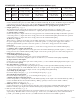
UL 294
(File # BP6714)
UL Listed for Access Control
System Units.
“Signal Equipment” Evaluated
to CSA Standard C22.2
No.205-M1983