ACM Series Access Power Controllers with Power Supplies Installation Guide Models Include: • AL400ULACM - 12VDC @ 4 amp - or 24VDC @ 3 amp Fused Outputs • AL1012ULACM - 12VDC @ 10 amp. - Fused Outputs • AL600ULACM - 12VDC or 24VDC @ 6 amp. - Fused Outputs • AL1024ULACM - 24VDC @ 10 amp. - Fused Outputs For a red enclosure, add an “R” suffix to the part # e.g. AL1024ULACMR Rev.
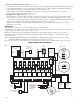
Overview: These units distribute and switch power to access control systems and accessories. They convert a 115VAC 60Hz input into eight (8) independently controlled 12VDC or 24VDC fuse protected outputs. These power outputs can be converted to dry form “C” contacts. Outputs are activated by an open collector sink or normally open (NO) dry trigger input from an Access Control System, Card Reader, Keypad, Push Button, PIR, etc.
• Zero voltage drop when unit switches over to battery backup (AC failure condition). • Thermal and short circuit protection with auto reset. • AC input and DC output LED indicators. • AC fail supervision (form "C" contact). • Battery fail and battery presence supervision (form "C" contact). • Enclosure accommodates up to two (2) 12AH batteries. Enclosure dimensions: 15.5"H x 12"W x 4.
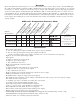
AL1024ULACM - (refer to AL1024ULACM Battery Size Calculation Worksheet, pg. 9) Voltage Stand-by Battery 15 mins. Stand-by / 5 mins. Alarm 4 hr. Stand-by / 5 mins. Alarm 24 hr. Stand-by / 5 mins. Alarm 60 hr. Stand-by / 5 mins. Alarm 24VDC 12 AH 7.7 amp / 9.7 amp 1.2 amp / 9.7 amp ------------------------- ------------------------- Voltage Stand-by Battery 15 mins. Stand-by / 5 mins. Alarm 4 hr. Stand-by / 5 mins. Alarm 24 hr. Stand-by / 5 mins. Alarm 60 hr. Stand-by / & 5 mins.
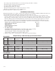
10. Battery and AC Supervision output (Fig. 2, pg. 6): It is required to connect supervisory trouble reporting devices to outputs marked [AC Fail, BAT FAIL] supervisory relay outputs marked [NC, C, NO] to appropriate notification devices. Use 22 AWG to 18 AWG for AC Fail & Low/No Battery reporting. Cut “AC delay” jumper to delay report 6 hour. Note:A tamper switch must be installed and connected to the appropriate notification device to report a trouble condition when the enclosure door is open. 11.
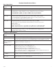
LED Diagnostics: Power Supply Board LED Red (DC) Green (AC) Power Supply Status ON ON Normal operating condition. ON OFF Loss of AC, Stand-by battery supplying power. OFF ON No DC output. Short circuit or thermal overload condition. OFF OFF No DC output. Loss of AC. Discharged battery. ACM8 Access Power Controller LED ON OFF LED 1- LED 8 (Red) Output relay(s) energized. Output relay(s) de-energized. Trg (Green) FACP input triggered (alarm condition). FACP normal (non-alarm condition).
Terminal Identification Tables: Power Supply Board Terminal Legend Function/Description L, G, N Connect 115VAC 60Hz to these terminals: L to hot, N to neutral, G to ground. - DC + AL400ULACM - 12VDC @ 4 amp or 24VDC @ 3 amp to ACM8 board (power limited). AL600ULACM - 12VDC/24VDC @ 6 amp to ACM8 board (non-power limited). AL1012ULACM - 12VDC @ 10 amp to ACM8 board (non-power limited). AL1024ULACM - 24VDC @ 10 amp to ACM8 board (non-power limited). AC FAIL NC, C, NO Indicates loss of AC power, e.g.
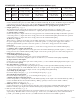
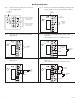
Hook-up Diagrams: Fig. 3 Optional hook-up using two (2) isolated power supply inputs: Fig. 4 Polarity reversal input from FACP signaling circuit output (polarity is referenced in alarm condition): CUT JUMPERS J1 AND J2 CUT JUMPER J3 J2 ISOLATED POWER INPUT 12 OR 24 VAC OR VDC (ACM8 POWER) J1 INTERFACE J3 TRG Fig. 5 Normally Open - Non-Latching FACP trigger input: Fig.
AL1024ULACM Battery Size Calculation Worksheet. A. AL1024ULACM internal current consumption (stand-by) ______________________ .35 A B. Load current consumption (stand-by) ______________________ A C. Stand-by time required (hours) ______________________ H D. Battery capacity required for stand-by (A+B)*C ______________________ AH E. AL1024ULACM internal power consumption (Alarm) ______________________ .35 A F. Load current consumption (Alarm) ______________________ A G.
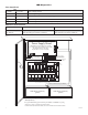
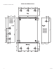
Enclosure Dimensions: 15.5”H x 12”W x 4.5”D 1.285 1.
Notes: ACMseries - 11 -
Notes: Altronix is not responsible for any typographical errors. Altronix Corp. 140 58th Street, Brooklyn, New York 11220 USA, 718-567-8181, fax: 718-567-9056 web site: www.altronix.com, e-mail: info@altronix.com, Lifetime Warranty, Made in U.S.A.