
Installation Instructions
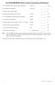

ACMCB220 Series Installation Guide - 7 -
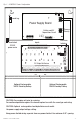
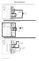
L G N
AC
+BAT-
DC
+ DC -
BAT FAIL NC C NO NC C NO AC FAIL
BAT
OFF - 24V
ON - 12V
ON
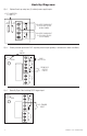
OUTPUT 1 OUTPUT 2 OUTPUT 3 OUTPUT 4 OUTPUT 5 OUTPUT 6 OUTPUT 7 OUTPUT 8
NC C NO COM NC C NO COM NC C NO COM NC C NO COM NC C NO COM NC C NO COM NC C NO COM NC C NO COM
IN GND IN GND IN GND IN GNDIN GND IN GND IN GND IN GND
1 2 3 4
5 6 7 8
INPUT
TRIGGER
10A 250V
+INP- T + RET-
NO C NC
FACP INTERFACE
Power Control
- + - +
F1 F2 F3 F4 F5 F6 F7 F8
MAIN
TRG
FACP
1 2 3 4
1 2 3 4
ON
ON
1 2 3 4
1 2 3 4
ON
ON
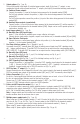
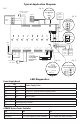
Fire Alarm
Interface
Battery and AC
Supervision Circuit
Observe
Polarity
Power Supply Board
DC Output to Devices
Inputs
Ground Lug
Unswitched
220VAC
power mains
Optional Rechargeable
12VDC Stand-by Battery
Optional Rechargeable
12VDC Stand-by Battery
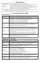
CAUTION: De-energize unit prior to servicing.
For continued protection against fire hazard replace fuse with the same type and rating.
CAUTION: Optional rechargeable stand-by batteries must match
the power supply output voltage setting.
Keep power-limited wiring separate from non power-limited. Use minimum 0.25" spacing.
Fig. 2 - ACMCB220 Series Configuration