
Installation Instructions
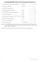

- 6 - ACMCB220 Series Installation Guide
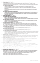
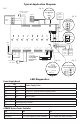
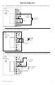
Typical Application Diagram:
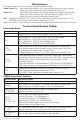
LED Diagnostics:
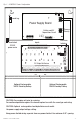
Power Supply Board
LED
Power Supply Status
Red (DC) Green (AC)
ON ON Normal operating condition.
ON OFF Loss of AC. Stand-by battery supplying power.
OFF ON No DC output. Short circuit or thermal overload condition.
OFF OFF No DC output.
Red (Bat) Battery Status
ON Normal operating condition.
OFF Battery fail/low battery.
ACM8CB Access Power Controller
LED ON OFF
LED 1 - LED 8 (Red) Output relay(s) energized. Output relay(s) de-energized.
Trg (Green) FACP input triggered (alarm condition). FACP normal (non-alarm condition).
Normally Open (N.O.)
Door Releasing
Device
Mag.
Lock
MAG. LOCK
Electric
Strike
Electromagnetic
Door Holders
UL Listed
Power Supply
For this application
corresponding
fuse F8 must be
removed.
Keypad
AC or DC
Power
Supply
(req'd.)
AC or DC
Power
Supply
(optional)
NC
NO
C
Access Control Panel
Output
Relay
FACP
(Fire Alarm
Control
Panel)
NC C NO COM
OUTPUT 1
LED1
F1
NC C NO COM
OUTPUT 2
IN GND
1
IN GND
2
IN GND
3
IN GND
4
IN GND
5
IN GND
6
IN GND
7
MAIN
IN GND
8
LED2
LED3
LED4
LED5
LED6
LED7
LED8
J2
FACP
NC C NO COM
OUTPUT 3
NC C NO COM
OUTPUT 4
NC C NO COM
OUTPUT 5
NC C NO COM
OUTPUT 6
NO C NC + INP --- T + RET -
NC C NO COM
OUTPUT 7
NC C NO COM
OUTPUT 8
--- +
Power
--- +
Control
F2
F3
F6 F7 F8
F4
F5
J1
J3
FACP INTERFACE
10A 250V
FACP Dry
Form "C" Output
NO C NC
FACP
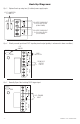
1 2 3 4
ON
1 2 3 4
ON
Enabled
Disabled
FACP Interface
SW1-SW8
ON
1
ON
1
J2
--- +
Control
J1
Intact = One P/S Input
Cut = Dual P/S Input
NC C NO COM
OUTPUT 8
J3
Intact = DC Input
Cut = AC Input
TRG
FACP
Intact = Dry Input
Cut = Wet Input
LED1
LED2
LED3
LED4
LED5
LED6
LED7
LED8
Fig. 1
Fig. 1b
Fig. 1a
Fig. 1cFig. 1d