
Installation Instructions

ACMCB220 Series Installation Guide - 3 -
Installation Instructions:
Wiring methods shall be in accordance with the National Electrical Code/NFPA 70/NFPA 72/ANSI, and with all
local codes and authorities having jurisdiction. Product is intended for indoor use only.
1. Mount unit in desired location. Mark and predrill holes in the wall to line up with the top two keyholes in
the enclosure. Install two upper fasteners and screws in the wall with the screw heads protruding. Place the
enclosure’s upper keyholes over the two upper screws, level and secure. Mark the position of the lower
two holes. Remove the enclosure. Drill the lower holes and install the three fasteners. Place the enclosure’s
upper keyholes over the two upper screws. Install the two lower screws and make sure to tighten all
screws (Enclosure Dimensions, pg. 12). Secure enclosure to earth ground.
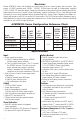
It is recommended to first review the following tables to facilitate installation:
Output Voltage and Stand-by Specifications Charts (pg. 3)
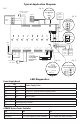
Typical Application Diagram (pg. 6)
LED Diagnostics (pg. 6)
Terminal Identification Tables (pg. 5)
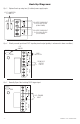
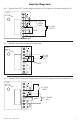
Hook-up Diagrams (pg. 8-9)
2. Set output voltage:
AL400ACMCB220 and AL600ACMCB220: set desired DC output voltage by setting switch SW1 to the
appropriate position on the power supply board. AL1012ACMCB220 is factory set at 12VDC and
AL1024ACMCB220 is factory set at 24VDC (Output Voltage and Stand-by Specification Charts below).
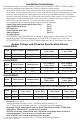
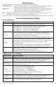
Output Voltage and Stand-by Specification Charts:
AL400ACMCB220
Voltage Switch Position Stand-by Battery
4 hr. Stand-by /
5 mins. Alarm
24 hr. Stand-by /
5 mins. Alarm
12VDC SW1 - ON 40AH 3.5A / 3.5A 1A / 3.5A
24VDC SW1 - OFF 40AH 2.75A / 2.75A 1A / 3A
AL600ACMCB220
Voltage Switch Position Stand-by Battery
4 hr. Stand-by /
5 mins. Alarm
24 hr. Stand-by /
5 mins. Alarm
12VDC SW1 - ON 40AH 5.5A / 5.5A 0.5A / 5.5A
24VDC SW1 - OFF 40AH 5.75A / 5.75A 0.75A / 5.75A
AL1012ACMCB220
Voltage Switch Position Stand-by Battery
4 hr. Stand-by /
5 mins. Alarm
24 hr. Stand-by /
5 mins. Alarm
12VDC N/A 40AH 9.5A / 9.5A 0.5A / 9.5A
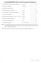
AL1024ACMCB220 (refer to AL1024ACMCB220 Battery Size Calculation Worksheet, pg. 10).
Voltage
Stand-by
Battery
15 mins. Stand-by /
5 mins. Alarm
4 hr. Stand-by /
5 mins. Alarm
24 hr. Stand-by /
5 mins. Alarm
60 hr. Stand-by /
5 mins. Alarm
24VDC 12AH 7.7A / 9.7A 1.2A / 9.7A – –
24VDC 65AH – 7.7A / 9.7A 1.2A / 9.7A 200mA / 9.7A
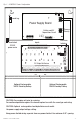
3. Connect AC (Fig. 2, pg. 7):
Connect unswitched AC power (220VAC, 50/60Hz) to terminals marked [L, N].
Use 14 AWG or larger for all power connections. Secure green wire lead to ground lug.
Keep power-limited wiring separate from non power-limited wiring (220VAC, 50/60Hz Input,
Battery Wires). Minimum 0.25” spacing must be provided.
CAUTION: Do not touch exposed metal parts. Shut branch circuit power before installing or
servicing equipment. There are no user serviceable parts inside.
Refer installation and servicing to qualified service personnel.
4. Measure voltage before connecting devices. This helps avoiding potential damage.