
Installation Instructions Owner's manual


AL1012ULXseries - 5 -
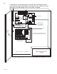
N
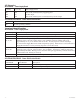
COMMON POWER OUTPUTS
P
FUSED POWER OUTPUTS
D1
INPUT
R1
LED
3.5A 250V 3.5A 250V
3.5A 250V
1
2
DC Output to devices
(non-power limited)
G
reen
L
ead
Battery connection (non-power limited)
Door
Wire Strap
(from
Enclosure
to Door)
115 power
mains
(non-power
limited)
Divider
CAUTION: De-energize unit prior to servicing. For continued protection
against risk of electric shock and fire hazard replace fuse with the same type
and rating 3.5A, 250V. Replace fuse cover before energizing.
Class 1
Provide 1/4" separation between
power limited and all other circuits
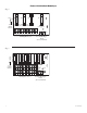
Battery and AC
Supervision Circuit
(power limited)
Use separate knockout
Non-power limited
+ DC ---
B
AT FAIL
NC C NO NC C NO
+ BAT ---
DC
A
C FAIL
L
G N
AC
3.5A 250V
Green Lead
Keep power limited wiring separate from non-power limited. Use minimum .25" spacing.
12VDC Rechargeable Battery
(optional)
Fig. 1