
Installation Instructions Owner's manual


- 4 - AL1012ULXseries
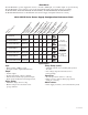
LED Diagnostics:
AL1012ULXB - Power Supply Board
Red (DC) Green (AC) Power Supply Status
ON ON Normal operating condition
ON OFF Loss of AC, Stand-by battery supplying power
OFF ON No DC output
OFF OFF Loss of AC. Discharged or no stand-by battery. No DC output.
PD4/PD4CB/PD8/PD8CB - Power Distribution Module
Green Power Distribution Module Status
ON Normal operating condition.
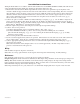
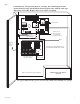
Terminal Identification:
AL1012ULXB - Power Supply Board
Terminal Legend Function/Description
L, G, N Connect 115VAC to these terminals: L to Hot, N to Neutral, G to ground.
- DC + 12VDC @ 10 amp continuous non-power limited output.
AC FAIL Indicates loss of AC power, e.g. connect to annuciator/alarm panel. Relay normally energized
NC, C, NO when AC power is present. Contact rating 1 amp @ 30VDC. AC Fail condition will report
approximately one (1) to one minute after loss of AC. To delay report for 6 hours cut jumper
J1 on the Power Supply Board (AC trouble output delay option). If this mode is selected the Power
Supply Board must be reset by removing all power to it for 30 seconds.
BAT FAIL Indicates low battery condition, e.g. connect to alarm panel. Relay normally energized
NO, C, NC when DC power is present. Contact rating 1 amp @ 30VDC. Low battery conditions will report
appro
ximately 10.5VDC Battery presence detection will report approimately 1 minute after battery
remains undetected (missing or removed).
- BAT + Stand-by battery connections. Maximum charge rate .7 amp.
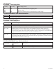
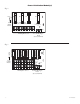
PD4/PD4CB/PD8/PD8CB - Power Distribution Module
Terminal Legend Function/
PD4/PD4CB PD8/PD8CB Description
1P to 4P 1P to 8P Positive DC power outputs.
1N to 4N 1N to 8N Negative DC power outputs.