
Installation Instructions

Agency Listings:
• ULRecognizedcomponentforAccessControl
SystemUnits(UL294).
Input:
• Input115VAC/60Hz,2.6amp.
Output:
• 12VDCoutput.
• 10ampcontinuoussupplycurrent.
• Filteredandelectronicallyregulatedoutput.
Fuse Ratings:
• InputFuse:250VAC,5A
• OutputFuse:32VDC,15A
Battery Backup:
• Built-inchargerforsealedleadacidorgeltypebatteries.
• Maximumchargecurrent0.7amp.
• Automaticswitchovertostand-bybattery
whenACfails.
• Zerovoltagedropwhenswitchedovertobatterybackup.
Visual Indicators:
• ACinputandDCoutputLEDindicators.
Supervision:
• ACfailsupervision(form“C”contacts).
• Batterypresencesupervision(form“C”contacts).
Additional Features:
• Shortcircuitandthermaloverloadprotection.
Board Dimensions (W x L x H approximate):
4.5”x7.25”x1.75”(114.3mmx184.15mmx44.45mm)
Stand-by Specifications:
When12VDC/12AHbatteryisused,theunitprovides30minutesofbackup@10amp.
Installation Instructions:
TheAL1012ULXBmustbeinstalledinaccordancewitharticle760oftheNationalElectricalCode,ANSI/NFPA70and
allapplicableLocalCodes.
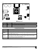
1. MounttheAL1012ULXBinthedesiredlocation/enclosure.
2. ConnectunswitchedACpower(115VAC/60Hz)totheterminalsmarked[L,G,N](Fig. 1, pg. 2).Use18AWGor
largerforallpowerconnections(Battery,ACinput,DCoutput).Use22AWGto18AWGforpower-limitedcircuits
(ACFail/LowBatteryreporting).
Keep power-limited wiring separate from non power-limited wiring (115VAC / 60Hz Input, Battery Wires).
Minimum 0.25” spacing must be provided.
CAUTION: Do not touch exposed metal parts. Shut branch circuit power before installing or servicing equipment.
There are no user serviceable parts inside. Refer installation and servicing to qualified service personnel.
3. Measureoutputvoltagebeforeconnectingdevices.Thishelpsavoidingpotentialdamage.
4. Connectdevicestobepoweredtotheterminalsmarked[+DC–](Fig. 1, pg. 2).
5. ForAccessControlapplicationsbatteriesareoptional.Whenbatteriesarenotused,alossofACwillresultinthe
lossofoutputvoltage.Whentheuseofstand-bybatteriesisdesired,theymustbeleadacidorgeltype.Connect
batterytotheterminalsmarked[+BAT–](Fig. 1, pg. 2).
6. Ifitisrequiredtoconnectappropriatesignalingnotificationdevicesto[ACFAIL]and[BATFAIL]supervisoryrelay
outputs(Fig. 1),use22AWGto18AWGwires.
Maintenance:
Unitshouldbetestedatleastonceayearfortheproperoperationasfollows:
Output Voltage Test: Undernormalloadconditions,theDCoutputvoltageshouldbecheckedforproper
voltagelevel(13.2volts).
Battery Test: Undernormalloadconditionscheckthatthebatteryisfullycharged,checkspecified
voltagebothatbatteryterminalandattheboardterminalsmarked[+BAT-]toensurethere
isnobreakinthebatteryconnectionwires.
Note: Maximumchargingcurrentunderdischargeis0.7amp.
Note: Expectedbatterylifeis5years;however,itisrecommendedchangingbatteriesin4years
orlessifneeded.
AL1012ULXB
UL Recognized Power Supply/Charger
Overview:
TheAL1012ULXBpowersupplyconvertsa115VAC/60Hzinputintoa12VDCnonpower-limitedoutput
(seespecifications).
Specifications: