ACMJ Series Access Power Controllers with Power Supplies Installation Guide Models Include: • AL400ULACMJ • AL600ULACMJ - 12VDC @ 4 amp - 12VDC or 24VDC @ 6 amp. or 24VDC @ 3 amp - Fused Outputs - Fused Outputs • AL1012ULACMJ • AL1024ULACMJ - 12VDC @ 10 amp. - 24VDC @ 10 amp. - Fused Outputs - Fused Outputs Rev.
Overview: These units distribute and switch power to access control systems and accessories. They convert a 115VAC 60Hz input into eight (8) independently controlled 12VDC or 24VDC fuse protected outputs. These power outputs can be converted to dry form “C” contacts. Outputs are activated by an open collector sink or normally open (NO) dry trigger input from an Access Control System, Card Reader, Keypad, Push Button, PIR, etc.
Installation Instructions: Wiring methods shall be in accordance with the National Electrical Code/NFPA 70/NFPA 72/ANSI, and with all local codes and authorities having jurisdiction. Product is intended for indoor use only. 1. Mount unit in desired location. Mark and predrill holes in the wall to line up with the top two keyholes in the enclosure. Install two upper fasteners and screws in the wall with the screw heads protruding.
(b) Form “C” outputs: When form “C” outputs are desired the corresponding output fuse (1-8) must be removed. Connect negative (–) of the power supply directly to the locking device. Connect the positive (+) of the power supply to the terminal marked [C]. For Fail-Safe operation connect the positive (+) of the device being powered to the terminal marked NC]. For Fail-Secure operation connect the positive (+) of the device being powered to the terminal marked [NO].
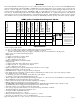
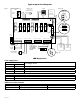
Typical Application Diagram: FACP Dry Form "C" Output FACP C (Fire Alarm Control Panel) NO NO C NC FACP OUTPUT RELAY Fig. 1a KEYPAD NORMALLY OPEN N.O. DOOR RELEASING DEVICE ACCESS CONTROL PANEL NO C NC + INP --- T + RET FACP INTERFACE NC J3 TRG IN GND IN GND IN GND IN GND 1 2 3 4 F1 F2 F3 IN GND IN GND IN GND IN GND 5 6 7 8 F4 F5 F6 F7 F8 ON ON 2 3 4 1 2 3 4 SW1-SW8 ON 1 3.5A 250V 3.5A 250V 3.5A 250V 3.5A 250V 3.5A 250V 3.5A 250V 3.5A 250V 1 Fig. 1 3.
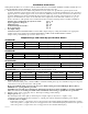
Fig. 2 CAUTION: De-energize unit prior to servicing. For continued protection against fire hazard replace fuse with the same type and rating. Divider Fire Alarm Interface Optional Rechargeable Stand-by Battery NC C NO COM NC C NO COM OUTPUT 5 OUTPUT 6 NC C NO COM NC C NO COM OUTPUT 3 OUTPUT 4 LED4 LED3 LED2 LED1 3.5A 250V F1 + DC – DC Output to devices (non power-limited) J2 LED8 LED7 LED6 LED5 3.5A 250V 3.5A 250V 3.5A 250V 3.5A 250V 3.5A 250V 3.5A 250V 3.
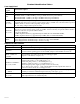
Terminal Identification Tables: Power Supply Board Terminal Legend L, N + DC – AC FAIL NC, C, NO BAT FAIL NC, C, NO + BAT – Function/Description Connect 115VAC 60Hz to these terminals: L to hot, N to neutral. AL400ULACMJ - 12VDC @ 4 amp or 24VDC @ 3 amp to ACM8 board (power-limited). AL600ULACMJ - 12VDC/24VDC @ 6 amp to ACM8 board (non power-limited). AL1012ULACMJ - 12VDC @ 10 amp to ACM8 board (non power-limited). AL1024ULACMJ - 24VDC @ 10 amp to ACM8 board (non power-limited).
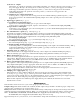
Hook-Up Diagrams: Fig. 3 Optional hook-up using two (2) isolated power supply inputs: Fig. 4 Polarity reversal input from FACP signaling circuit output (polarity is referenced in alarm condition): CUT JUMPERS J1 AND J2 CUT JUMPER J3 J2 ISOLATED POWER INPUT 12 OR 24 VAC OR VDC (ACM8 POWER) J1 INTERFACE J3 TRG Fig. 5 Normally Open - Non-Latching FACP trigger input: Fig. 6 Normally Open FACP Latching trigger input with reset: (This output has not been evaluated by UL) J3 INTERFACE J3 TRG N.O.
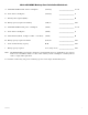
AL1024ULACMJ Battery Size Calculation Worksheet. A. AL1024ULACMJ internal current consumption (stand-by) ______________________________ 0.35 A B. Load current consumption (stand-by) ______________________________ A C. Stand-by time required (Hours) ______________________________ H D. Battery capacity required for stand-by (A+B)*C ______________________________ AH E. AL1024ULACMJ internal power consumption (Alarm) ______________________________ 0.35 A F.
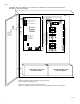
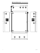
Enclosure Dimensions (H x W x D approximate): 18” x 14.5” x 4.625” (457.2mm x 368.3mm x 117.48mm) 14.5” (368.3mm) 1.5” (38.1mm) 2.5” (63.5mm) 2.5” (63.5mm) 1.5” (38.1mm) 4.5” (114.3mm) 1.0” (25.4mm) 1.25” (31.75mm) 1.5” (38.1mm) 1.25” (31.75mm) 1.5” (38.1mm) 1.0” (25.4mm) 1.0” (25.4mm) 1.5” (38.1mm) 2.5” (63.5mm) 8.5” (215.9mm) 6.0” (152.4mm) 18.0” (457.2mm) 18.0” (457.2mm) 18.0” (457.2mm) 1.0” (25.4mm) 1.0” (25.4mm) 1.0” (25.4mm) 2.75” (69.85mm) 1.5” (38.1mm) 14.5” (368.3mm) 4.
Notes: ACMJ series - 11 -
Notes: Altronix is not responsible for any typographical errors. 140 58th Street, Brooklyn, New York 11220 USA, 718-567-8181, fax: 718-567-9056 web site: www.altronix.com, e-mail: info@altronix.com, Lifetime Warranty, Made in U.S.A.