
Installation Instructions


ACMCB220 Series Installation Guide - 5 -
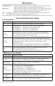
Maintenance:
Unit should be tested at least once a year for the proper operation as follows:
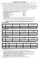
Output Voltage Test: Under normal load conditions, the DC output voltage should be checked for proper
voltage level (Output Voltage and Stand-by Specification Charts, pg. 3).
Battery Test: Under normal load conditions check that the battery is fully charged, check specified
voltage at the battery terminals and at the board terminals marked [+ BAT –] to
ensure that there is no break in the battery connection wires.
Note: AL400XB2V, AL600XB220, AL1012XB220 (Power Supply Board) maximum charge current is 0.7A.
AL1024XB2V (Power Supply Board) maximum charge current is 3.6A.
Expected battery life is 5 years, however it is recommended to change batteries within 4 years or less if necessary.
Terminal Identification Tables:
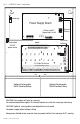
Power Supply Board
Terminal Legend Function/Description
L, N Connect 220VAC, 50/60Hz to these terminals: L to hot, N to neutral.
+ DC –
AL400ACMCB220 - 12VDC @ 4A or 24VDC @ 3A to ACM8CB board.
AL600ACMCB220 - 12VDC/24VDC @ 6A to ACM8CB board.
AL1012ACMCB220 - 12VDC @ 10A to ACM8CB board.
AL1024ACMCB220 - 24VDC @ 10A to ACM8CB board.
AC FAIL
NC, C, NO
Used to notify loss of AC power, e.g. connect to audible device or alarm panel.
Relay normally energized when AC power is present. Contact rating 1A @ 28VDC.
AC or brownout fail is reported within 1 minute of event.
To delay reporting of up to 6 hrs. cut “AC delay” jumper and reset power to unit.
BAT FAIL
NC, C, NO
Used to indicate low battery condition, e.g. connect to alarm panel. Relay normally
energized when DC power is present. Contact rating 1A @ 28VDC. A removed battery is
reported within 5 minutes. Battery reconnection is reported within 1 minute.
Low battery threshold:
12VDC output threshold set @ approximately 10.5VDC (N/A for AL1024ACMCB220),
24VDC output threshold set @ approximately 21VDC (N/A for AL1012ACMCB220).
+ BAT –
Stand-by battery connections. AL400XB2V, AL600XB220 and AL1012XB220
(Power Supply Board) maximum charge current is 0.7A.
AL1024XB2V (Power Supply Board) maximum charge current is 3.6A.
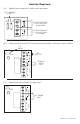
ACM8CB Access Power Controller
Terminal Legend Function/Description
– Power + 12VDC or 24VDC input from power supply board.
– Control +
These terminals can be connected to a separate power supply to provide isolated
operating power for the ACM8CB (jumpers J1and J2 must be removed).
TRIGGER INPUT 1 -
INPUT 8 IN, GND
From normally open and/or open collector sink trigger inputs
(request to exit buttons, exit pir’s, etc.).
OUTPUT 1 -
OUTPUT 8
NC, C, NO, COM
12 to 24 volts AC/DC trigger controlled outputs:
Fail-Safe [NC positive (+) & COM Negative (–)],
Fail-Secure [NO positive (+) & COM Negative (–)],
Auxiliary output [C positive (+) & COM Negative (v)]
(When using AC power supplies polarity need not be observed),
Contacts shown in a non-triggered state.
FACP INTERFACE
T, + INPUT –
Fire Alarm Interface trigger input from FACP. Trigger inputs can be normally open,
normally closed from an FACP output circuit (Fig. 4 through 8, pgs. 8-9).
FACP INTERFACE
NC, C, NO
Form “C” relay contact rated @ 1A 28VDC for alarm reporting.