ACMCB220 Series Access Power Controllers with Power Supplies Models Include: AL400ACMCB220 AL1012ACMCB220 AL600ACMCB220 AL1024ACMCB220 - 12VDC @ 4A or 24VDC @ 3A. - PTC Protected Outputs - 12VDC or 24VDC @ 6A. - PTC Protected Outputs - 12VDC @ 10A. - PTC Protected Outputs - 24VDC @ 10A. - PTC Protected Outputs For a red enclosure add an “R” suffix to the part #, e.g. AL1024ACMCBR220 Installation Guide Rev. 120115 More than just power.TM Installing Company: ________________ Service Rep.
Overview: Altronix ACMCB220 Series units distribute and switch power to access control systems and accessories. They convert a 220VAC (working range 198VAC - 256VAC), 50/60Hz input into eight (8) independently controlled 12VDC or 24VDC PTC protected outputs. Outputs are activated by an open collector sink or normally open (NO) dry trigger input from an Access Control System, Card Reader, Keypad, Push Button, PIR, etc.
Installation Instructions: Wiring methods shall be in accordance with the National Electrical Code/NFPA 70/NFPA 72/ANSI, and with all local codes and authorities having jurisdiction. Product is intended for indoor use only. 1. Mount unit in desired location. Mark and predrill holes in the wall to line up with the top two keyholes in the enclosure. Install two upper fasteners and screws in the wall with the screw heads protruding.
5. Output options (Fig. 1, pg. 6): The unit will provide either eight (8) switched power outputs, eight (8) dry form “C” outputs, or any combination of both switched power and form “C” outputs, plus eight (8) unswitched auxiliary power outputs. (a) Switched Power outputs: Connect the negative (–) input of the device being powered to the terminal marked [COM]. For Fail-Safe operation connect the positive (+) input of the device being powered to the terminal marked [NC].
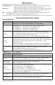
Maintenance: Unit should be tested at least once a year for the proper operation as follows: Output Voltage Test: Under normal load conditions, the DC output voltage should be checked for proper voltage level (Output Voltage and Stand-by Specification Charts, pg. 3).
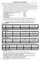
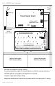
Typical Application Diagram: Fig. 1 Fig. 1a Intact = Dry Input Cut = Wet Input Normally Open (N.O.) Door Releasing Device Access Control Panel FACP (Fire Alarm Control Panel) FACP Keypad TRG C Fig.
ON OFF - 24V ON - 12V Fig.
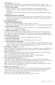
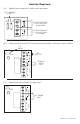
Hook-Up Diagrams: Fig. 3 Optional hook-up using two (2) isolated power supply inputs: CUT JUMPERS J1 AND J2 J2 J1 ISOLATED POWER INPUT 12 OR 24 VAC OR VDC (ACM8 POWER) ISOLATED POWER INPUT 12 OR 24 VAC OR VDC (LOCK POWER) Fig. 4 Polarity reversal input from FACP signaling circuit output (polarity is referenced in alarm condition): CUT JUMPER FACP OUTPUT EOL -- FROM FACP OUTPUT + CIRCUIT NO C NC FACP TRG INTERFACE FACP Fig. 5 Normally Open: Non-Latching FACP trigger input: N.O.
Hook-Up Diagrams: Fig. 6 Normally Open FACP Latching trigger input with reset (This output has not been evaluated by UL): FACP TRG NC N.O. TRIGGER INPUT N.C. RESET SWITCH NO C JUMPER Fig. 7 Normally Closed: Non-Latching FACP trigger input: NO C NC FACP TRG INTERFACE FACP N.C. DRY TRIGGER INPUT JUMPER Fig. 8 Normally Closed: Latching FACP trigger input with reset (This output has not been evaluated by UL): FACP TRG N.C. RESET SWITCH JUMPER ACMCB220 Series Installation Guide N.C.
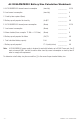
AL1024ACMCB220 Battery Size Calculation Worksheet: A. AL1024ACMCB220 internal current consumption (stand-by) __________ 0.35A B. Load current consumption (stand-by) __________ A C. Stand-by time required (Hours) __________ H D. Battery capacity required for stand-by (A+B)*C __________ AH E. AL1024ACMCB220 internal power consumption (Alarm) __________ 0.35A F. Load current consumption (Alarm) __________ A G. Alarm duration (Hours, example: 15 Min. = 0.
Notes: ACMCB220 Series Installation Guide - 11 -
Enclosure Dimensions (H x W x D approximate): 15.5” x 12” x 4.5” (393.7mm x 304.8mm x 114.3mm) 1.5” (38.1mm) 4.615” (117.2mm) 4.615” (117.2mm) 1.5” (38.1mm) 1.75” (44.5mm) 1.25” (31.8mm) 4.5” (114.3mm) 1.1” (27.9mm) 12.23” (310.6mm) 4.5” (114.3mm) 1.1” (27.9mm) 1.375” (34.9mm) 1.5” (38.1mm) 1.25” (31.8mm) 1.5” (38.1mm) 0.91” (23.1mm) 0.91” (23.1mm) 1.125” (28.6mm) 15.5” (393.7mm) 2.0” (50.8mm) 2.0” (50.8mm) 5.0” (127.0mm) 0.79” (20.1mm) 5.0” (127.0mm) 1.25” (31.8mm) 1.25” (31.8mm) 1.