AL1002ULADA NAC Power Extender Installation Guide (See Application Guide for additional information) Altronix Corp. 140 58th St. Brooklyn, NY Rev.
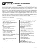
AL1002ULADA - NAC Power Extender Overview: The Altronix AL1002ULADA is an extremely cost effective 10 amp remote power supply/battery charger. It may be connected to any 12 or 24 volt Fire Alarm Control Panel (FACP). Primary applications include Notification Appliance Circuit (NAC such as strobes and horns) expansion support to meet ADA requirements. It also provides auxiliary power to support system accessories.
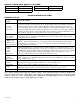
Power Supply Specifications: AC Input: Output: Battery: Stand-by/Alarm Current Consumption: EOL Resistor (end of line): Ground fault maximum test impedance: 120VAC 60Hz, 5 amp. Four (4) regulated supervised NAC output circuits, 24VDC, 2.5 amp maximum current. One (1) aux. special application 24VDC power output circuit 1 amp, non-supervised total output current must not exceed current 10 amp in Alarm Condition. Use two (2) 12VDC / 12AH or two (2) 12VDC / 7AH batteries connected in series. 130mA/300mA 2.
6. Connect FACP output to desired AL800LGK logic board inputs, and notification appliances to desired AL800LGK logic board outputs (see Application Guide). Note: The 2-wire horn/strobe sync mode will only synchronize horns, horn/strobes, strobes with synchronization capability. 7. For connection of smoke detectors, digital dialer see Optional Hookup Diagram, pg. 8.
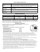
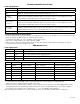
Amount of Notification Appliances per NAC: Amseco 27 per NAC* Faraday 39 per NAC* Gentex® 32 per NAC* *Not to exceed a maximum of 2.5 amp per NAC. AL800LGK Logic Board Terminal Legend System Sensor® CooperWheelock® 32 per NAC* 32 per NAC* Terminal Identification Table: Function/Description These terminals connect to the 12VDC or 24VDC FACP notification appliance circuit outputs. (Class A, Style Z or Class B, Style W, X, Y) Input trigger voltage is 8-33VDC @ 5mA min.
Terminal Identification Table: Power Supply Board* Terminal Legend Function/Description L, N Connect 120VAC to these terminals: L to hot, N to neutral (Fig. 2, pg. 7). - DC + 24VDC @ 10 amp in alarm non power-limited output (Fig. 2, pg. 7). AC FAIL NO, C, NC Form “C” dry contacts used to instantaneously signal the loss AC to local annunciation devices, with AC present terminals marked NO and C are open, NC and C are closed.
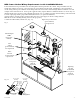
NEC Power-Limited Wiring Requirements for AL1002ULADA Models: Power-limited and non power-limited circuit wiring must remain separated in the cabinet. All power-limited circuit wiring must remain at least 0.25” away from any non power-limited circuit wiring. Furthermore, all power-limited circuit wiring and non power-limited circuit wiring must enter and exit the cabinet through different conduits. One such example of this is shown below.
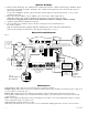
Optional hookups: 1- Battery and AC monitoring: AC or Battery Fail condition will cause the common trouble input [C “FAULT” NC] to report back to the FACP via input 1 and input 2. The common trouble input may also be used for other optional supervisory monitoring. To report AC and Battery Trouble connect the battery and AC Fail relay output shown in (Fig. 3a, Pg. 8) to the common trouble input.
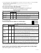
Battery Calculation Worksheet Device Number of Devices For each device use this formula: This column x This column = AL1002ULADA (Current draw from battery) 1 A AL1002 Current Auxiliary Devices B Stand-by Alarm Current Current Current per Device Equals Stand-by: 130mA Alarm: 300mA Current per number of devices. 130mA 300mA 130mA 300mA Refer to device manual for current ratings.
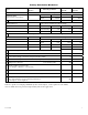
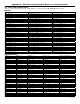
Appendix A - UL/cUL Listed Compatible Devices for Synchronization A-1 Strobes, Horns and Horn/Strobes Table A-1 below lists Strobes, Horns and Horn/Strobes compatible with AL1002ULADA NAC outputs.
Appendix A - UL/cUL Listed Compatible Devices for Synchronization (cont’d) A-1 Strobes, Horns and Horn/Strobes Table A-1 below lists Strobes, Horns and Horn/Strobes compatible with AL1002ULADA NAC outputs.
Appendix A - UL/cUL Listed Compatible Devices for Synchronization (cont’d) A-1 Strobes, Horns and Horn/Strobes Table A-1 below lists Strobes, Horns and Horn/Strobes compatible with AL1002ULADA NAC outputs.
Appendix B - UL Listed Compatible Devices B.1 Four (4) Wire Smoke Detectors Table B-1 below lists four (4) wire smoke detectors compatible with AL1002ULADA AUX output. Max Stand-by Alarm Current Current (mA) (mA) 30 50 0.05 23 0.05 23 0.05 35 0.05 35 0.05 50 0.05 50 0.05 * 0.05 * 10 28.4 17 38.
Notes: - 14 - AL1002ULADA
Notes: AL1002ULADA - 15 -
Enclosure Dimensions (H x W x D approx.): 15.5” x 12” x 4.5” (393.7mm x 304.8mm x 114.3mm) 1.5” (38.1mm) 4.615” (117.22mm) 4.615” (117.22mm) 1.5” (38.1mm) 1.75” (44.45mm) 1.375” (34.925mm) 1.125” (28.575mm) 1.25” (31.75mm) 4.5” (114.3mm) 12.23” (310.64mm) 1.1” (27.94mm) 0.91” (23.114mm) 1.5” (38.1mm) 4.5” (114.3mm) 1.1” (27.94mm) 1.25” (31.75mm) 0.91” (23.114mm) 2.0” (50.8mm) 1.5” (38.1mm) 15.5” (393.7mm) 2.0” (50.8mm) 5.0” (127.0mm) 5.0” (127.0mm) 1.1” (27.94mm) 1.25” (31.75mm) 0.