ACMS8 Series Sub-Assembly Access Power Controllers Installation Guide Models Include: ACMS8 - Eight (8) Fuse Protected Outputs ACMS8CB - Eight (8) PTC Protected Outputs Rev. 090518 More than just power.
Overview: Altronix ACMS8(CB) Access Power Controller’s dual input design allows power to be steered from two (2) independent low voltage 12 or 24VDC power sources to eight (8) independently controlled fuse (ACMS8) or PTC (ACMS8CB) protected outputs. Power outputs of ACMS8(CB) can be converted to dry form “C” contacts.
Installation Instructions: ON Wiring methods shall be in accordance with the National Electrical Code NFPA 70/NFPA 72/ ANSI / Canadian Electrical Code / CAN/ULC-S524/ULC-S527/ULC-S537, and with all local codes and authorities having jurisdiction. Product is intended for indoor dry use only. 1. Refer to Sub-Assembly Installation Instruction for mounting Rev. MS050913. Carefully review: Terminal Identification Table (pg. 4) Typical Application Diagram (pg. 7) LED Diagnostics (pg. 4) Hook-up Diagrams (pg.
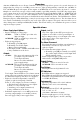
ON 9. Fire Alarm Interface options: Fig. 3 A normally closed [NC], normally open [NO] input or polarity reversal input from FACP signaling circuit will trigger selected outputs. To enable FACP Disconnect for FACP an output turn the corresponding DIP switch [SW1-SW8] ON. EN <--> DIS To disable FACP disconnect for an output turn the corresponding DIP switch 1 [SW1-SW8] OFF. Switch is located directly to the left of the 2 Fire Alarm Interface Terminals.
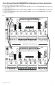
Daisy Chaining Two (2) ACMS8(CB) Dual Output Access Power Controllers: Use 18 AWG or larger UL Listed wire equipped with 1/4” UL Recognized quick connect terminals rated for proper voltage/current for all jumper connections. 1. Connect first ACMS8(CB) board’s spade lug marked [PWR1 +] to the second ACMS8(CB) board’s spade lug marked [PWR1 +]. 2. Connect first ACMS8(CB) board’s spade lug marked [COM –] to the second ACMS8(CB) board’s spade lug marked [COM –]. 3.
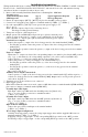
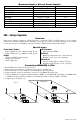
Maximum Output of Altronix Power Supplies: UL Listed or Recognized Power Supply AL400ULXB2 AL600ULXB AL1012ULXB AL1024ULXB2 eFlow4NB eFlow6NB eFlow102NB eFlow104NB VR6 Output Voltage 12VDC or 24VDC 12VDC or 24VDC 12VDC 24VDC 12VDC or 24VDC 12VDC or 24VDC 12VDC 24VDC 5VDC or 12VDC Max. Output Current 12VDC @ 4A or 24VDC @ 3A 6A 10A 10A 4A 6A 10A 10A 6A VR6 - Voltage Regulator Overview: VR6 voltage regulator converts a 24VDC input into a regulated 5VDC or 12VDC output.
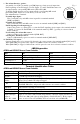
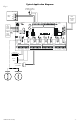
Typical Application Diagram: Fig. 6 Normally Open (N.O.) Door Releasing Device Access Control Panel C NO FACP NC (Fire Alarm Control Panel) +INP1-- PWR1+ +INP2-- +INP3-- +INP4-- +INP5-- +INP6-- +INP7-- +INP8-- ON C EOL JMP NC OUT8 OUT7 OUT6 FACP 3 COM-- 3 3 3 PWR1<--> PWR2 FACP EN <--> DIS 3 PWR1<--> PWR2 PWR1<--> PWR2 3 PWR1<--> PWR2 3 Altronix Corp.
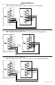
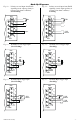
Hook-Up Diagrams: Fig. 7 - Daisy-chaining one or more ACMS8 units. EOL Jumper [EOL JMP] should be installed in the EOL position. Non-Latching. EOL JMP Jumper NC NC C Jumper C EOL JMP RST EOL +F +R GND GND -F -R FACP RST EOL +F +R GND GND -F -R FACP FACP FACP Fig. 8 - Daisy-chaining one or more ACMS8 units. EOL Jumper [EOL JMP] should be installed in the EOL position. Latching Single Reset. EOL JMP Jumper NC NC C N.O.
Hook-Up Diagrams: Fig. 10 - Polarity reversal input from FACP signaling circuit output (polarity is referenced in alarm conditiion). Non-Latching. Fig. 11 - FACP Polarity reversal input from FACP signaling circuit output (polarity is referenced in alarm condition). Latching. RST EOL +F +R GND GND -F -R + NC NC FACP Fig. 12 - FACP Normally Closed trigger input (Non-Latching). Fig. 13 - Normally Closed trigger input (Latching).
Notes: - 10 - ACMS8/CB Sub-Assembly
Notes: ACMS8/CB Sub-Assembly - 11 -
Notes: Altronix is not responsible for any typographical errors. 140 58th Street, Brooklyn, New York 11220 USA | phone: 718-567-8181 | fax: 718-567-9056 website: www.altronix.com | e-mail: info@altronix.com | Lifetime Warranty | Made in U.S.A.