
Installation Manual
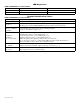


- 4 - ACM8/CB Sub-Assembly
(c) FACP Signaling Circuit input trigger:
Connect the positive (+) and negative (-) from the FACP signaling circuit output to the terminals marked [+ INP -].
Connect the FACP EOL to the terminals marked [+ RET -] (polarity is referenced in an alarm condition).
Jumper J3 must be cut (Fig. 3, pg. 6).
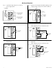
6. FACP Dry form “C” output (Fig. 1a, pg. 4):
Connect desired device to be triggered by the unit’s dry contact output to the terminals marked [NO] and [C]
FACP for normally open output or the terminals marked [NC] and [C] FACP for normally closed output.
Note:
This product is a UL Listed Sub-Assembly for use with Altronix UL Listed power supplies as indicated in the
installation manuals for the power supply.
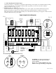
Typical Application Diagram:
WARNING: To reduce the risk of fire or
electric shock, do not expose the unit to
rain or moisture.
Replace fuses (ACM8/ACM8E models only)
with the same type and rating, 3.5 amp/250V.
NC
NO
C
Keypad
Normally Open
N.O. Door
Releasing Device
Access Control
Panel
Output
Relay
Mag.
Lock
MAG.
LOCK
Electric
Strike
Electromagnetic
Door Holders
AC or DC
Power
Supply
(optional)
AC or DC
Power
Supply
(req'd.)
FACP
(Fire Alarm
Control Panel)
UL Listed
Power Supply
For this application
corresponding
fuse F8 must be
removed.
ACM8CBACM8
FACP Dry
Form "C"
Output
NO C NC
FACP
LED1
F1
LED2
F2
3.5A 250V
3.5A 250V
LED1 LED2
2A 250V 2A 250V
Fire Alarm System Power Supply Unit
Also suitable for use as a
Access Control System Unit Subassembly.
39BA
Refer to Installation Instructions
IIACM8 - REV. 092503
NC C NO COM
OUTPUT 1
LED1
F1
NC C NO COM
OUTPUT 2
IN GND
1
IN GND
2
IN GND
3
IN GND
4
IN GND
5
IN GND
6
IN GND
7
MAIN
IN GND
8
LED2
LED3
LED4
LED5
LED6
LED7
LED8
J2
J1
TRG
NC C NO COM
OUTPUT 3
NC C NO COM
OUTPUT 4
NC C NO COM
OUTPUT 5
NC C NO COM
OUTPUT 6
NO C NC + INP --- T + RET -
NC C NO COM
OUTPUT 7
NC C NO COM
OUTPUT 8
--- +
Power
--- +
Control
F2
F3
F6 F7 F8
F4
F5
J3
FACP INTERFACE
10A 250V
FACP Interface Enabled
FACP Interface Disabled
SW1-SW8
ON
1
ON
1
1 2 3 4
ON
1 2 3 4
ON
LED1
LED2
LED3
LED4
LED5
LED6
LED7
LED8
Fig. 1
Fig. 1a